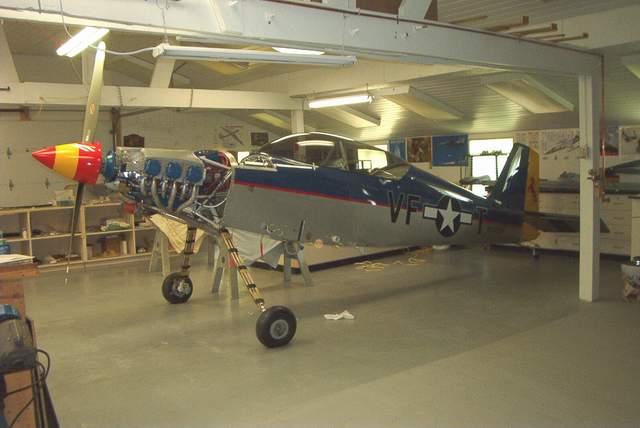
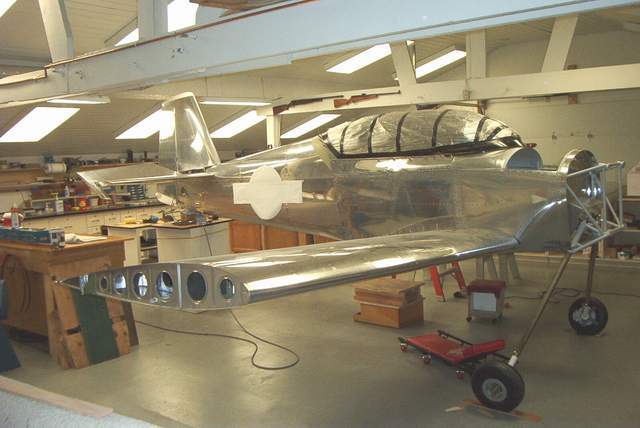
 Ready to roll...
Finishing
Moving to the airport:
Ready to roll...
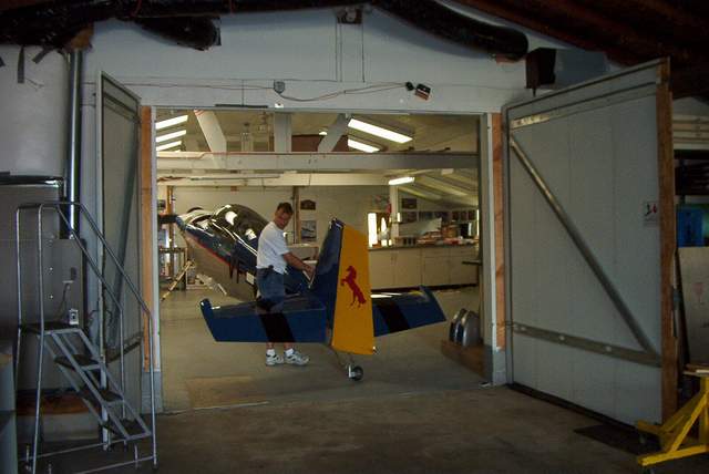
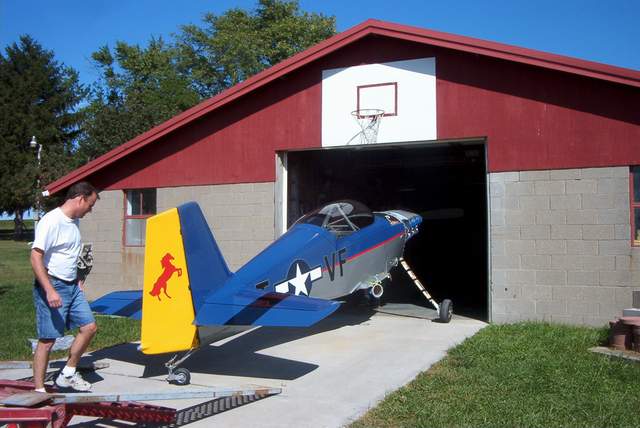 The birthing process... a breech baby!
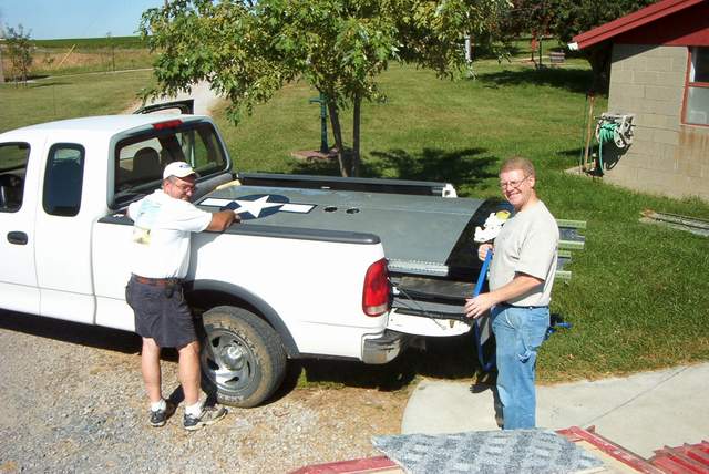 Holy cow! Those things are SHORT! They barely fill the pickup truck bed!
 Geez, I spend several years agonizing over every little detail of these
wings.... only to have these guys toss them in the back of a pickup truck!!!!
Can this be right!? Aw heck.... gotta get 'em to the airport! We've
got flying to do!
Geez, I spend several years agonizing over every little detail of these
wings.... only to have these guys toss them in the back of a pickup truck!!!!
Can this be right!? Aw heck.... gotta get 'em to the airport! We've
got flying to do!
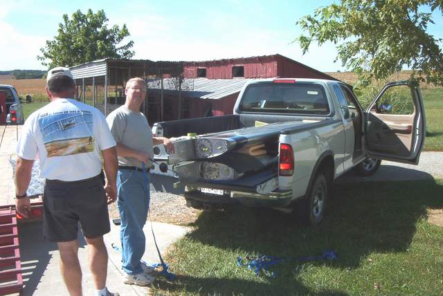
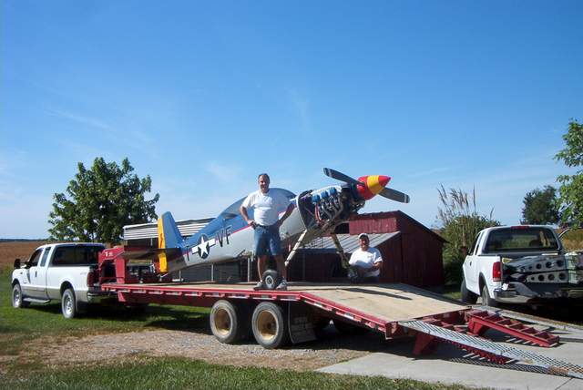 A back hoe trailer is THE way to go. A regular 16' flatbed trailer is
marginal at best.
A back hoe trailer is THE way to go. A regular 16' flatbed trailer is
marginal at best.
 The wings were barely even strapped in.... I cringe at the thought.
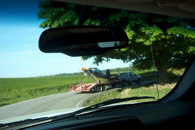
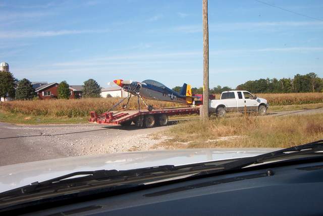 It's 17 miles to the airport. There are 21 turns to make to get there...
no kidding. You'd think I lived in the mountains.
It's 17 miles to the airport. There are 21 turns to make to get there...
no kidding. You'd think I lived in the mountains.
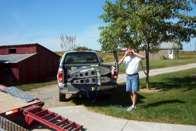
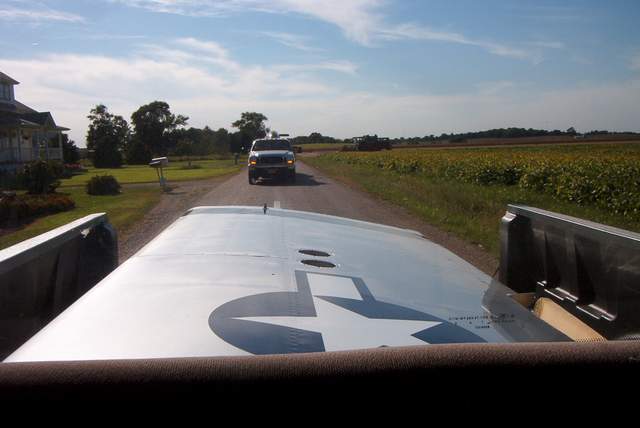
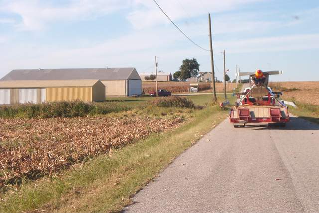
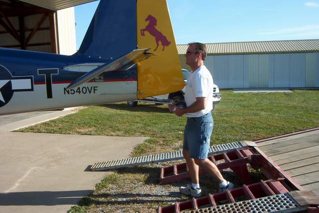
 This is what I looked like on the way to the airport. We
had three trucks. The lead truck was carrying the wings. In the middle was
the truck with the trailer that was carrying the fuselage. I was the
tail end truck carrying small parts. We were on a hilly country road with a
40mph speed limit. We were going about 35mph, slow but quick enough to not
cause any trouble for others. There was oncoming traffic.
This is what I looked like on the way to the airport. We
had three trucks. The lead truck was carrying the wings. In the middle was
the truck with the trailer that was carrying the fuselage. I was the
tail end truck carrying small parts. We were on a hilly country road with a
40mph speed limit. We were going about 35mph, slow but quick enough to not
cause any trouble for others. There was oncoming traffic.
The reason for the enraged expression is that some dumba$$ in a white Ford Ranger decided that passing a 3 truck (and trailer) convoy while going up a hill with oncoming traffic was a good idea. WTF!? Everyone motioned for him to stop/slow down... but you just can't communicate with F..ing idiots can you? Luckily, the oncoming traffic, a young lady in a Jeep, had enough sense to slow down when she saw the lead truck at the crest of the hill motioning to her to slow down. The brainless $&*% in the Ford Ranger had to slam on the brakes. The lady in the Jeep and the moron in the Ranger ended up nose to nose at the top of the hill, but did not collide.
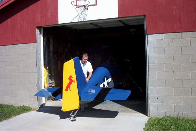
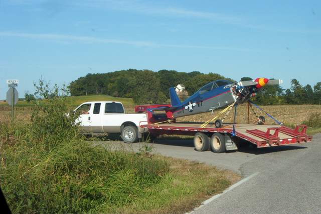
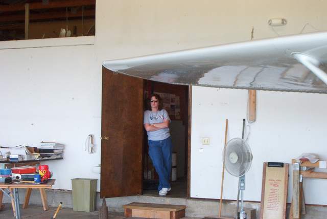
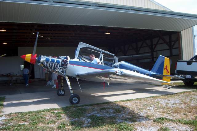
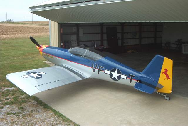
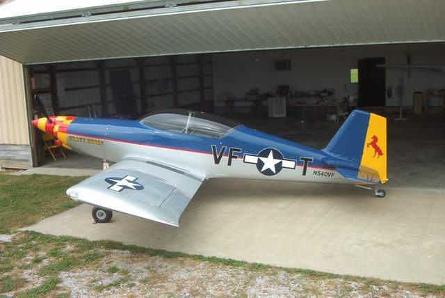
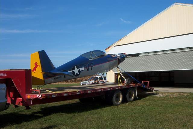 Arriving at the new home on 9-18-2004.
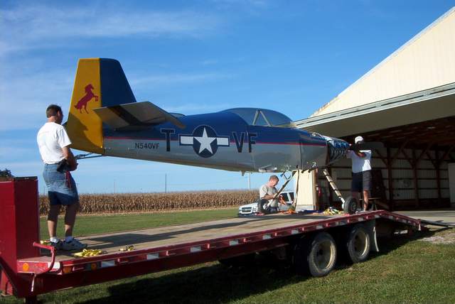
 It's easier to unload than to load.
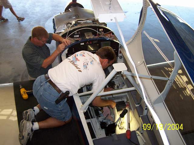
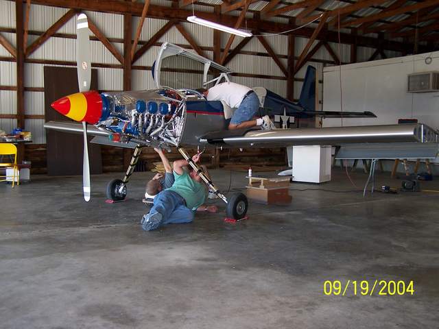
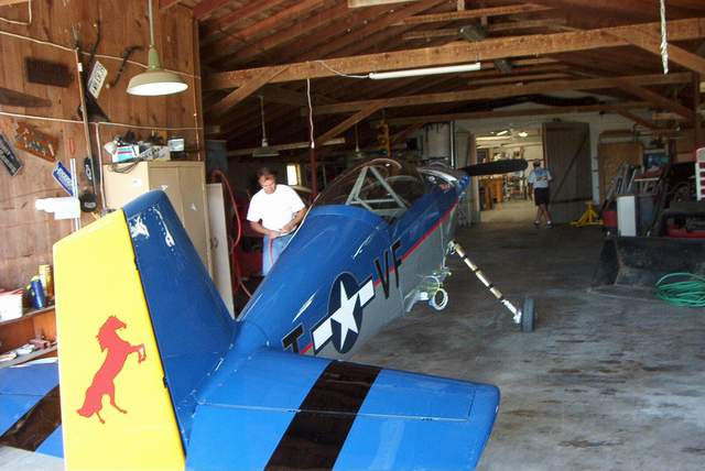
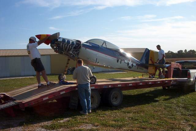
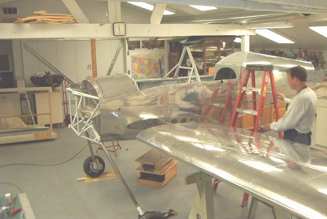
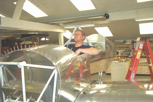
 Putting the wings on takes all freaking day. I wish that there were more
bolts to put in... 64 bolts just doesn't seem like enough. You'll find
that putting the bolts in will give you chest pains... from leaning over the
cockpit rail! I'm still sore. The alternative is to sit inside the
cockpit and have the seat belt attach bars sticking you in the butt. No thanks.
Putting the wings on takes all freaking day. I wish that there were more
bolts to put in... 64 bolts just doesn't seem like enough. You'll find
that putting the bolts in will give you chest pains... from leaning over the
cockpit rail! I'm still sore. The alternative is to sit inside the
cockpit and have the seat belt attach bars sticking you in the butt. No thanks.
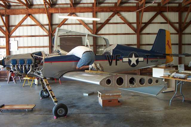
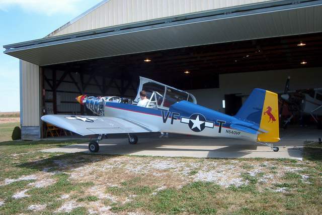
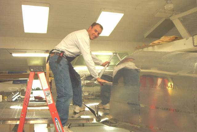
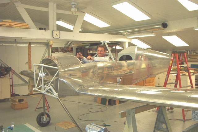
 Yippee! The wings are on!
 Take every tool you own to the airport. It still won't be enough.
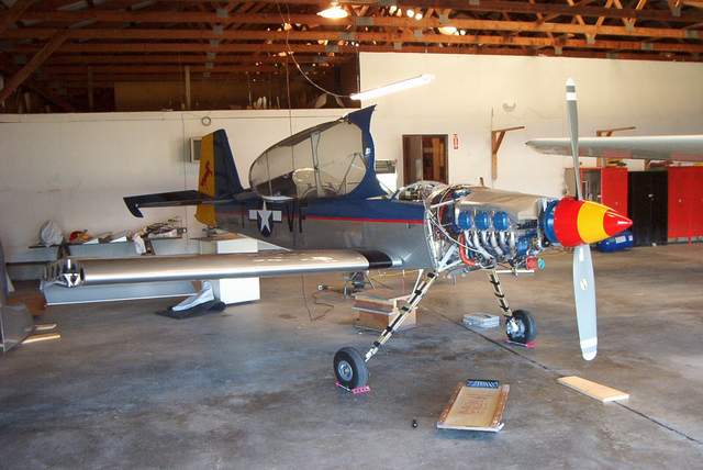
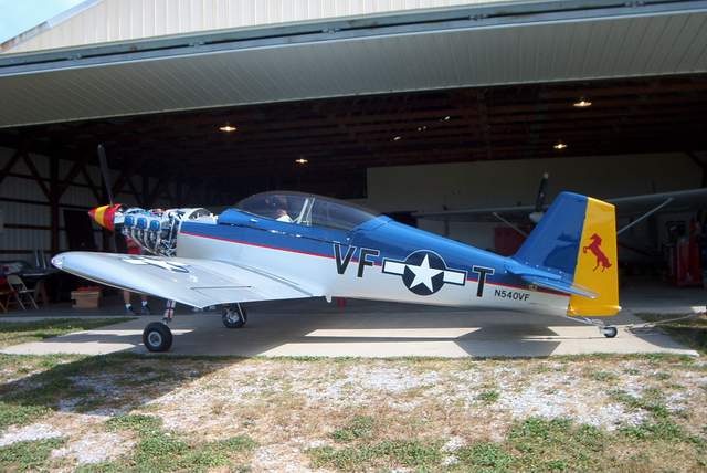
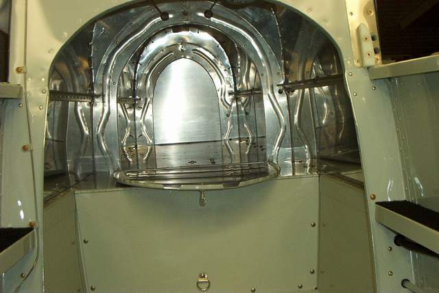
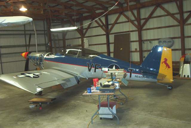 Words escape me. She's getting close!
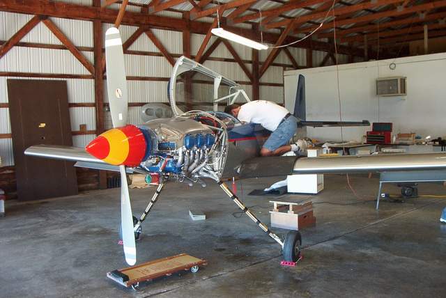
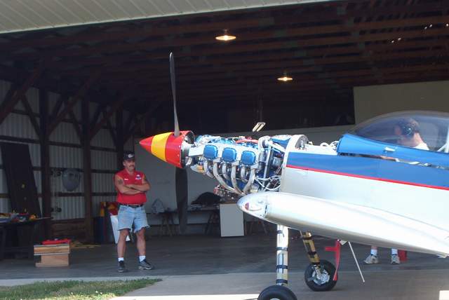
First engine start:
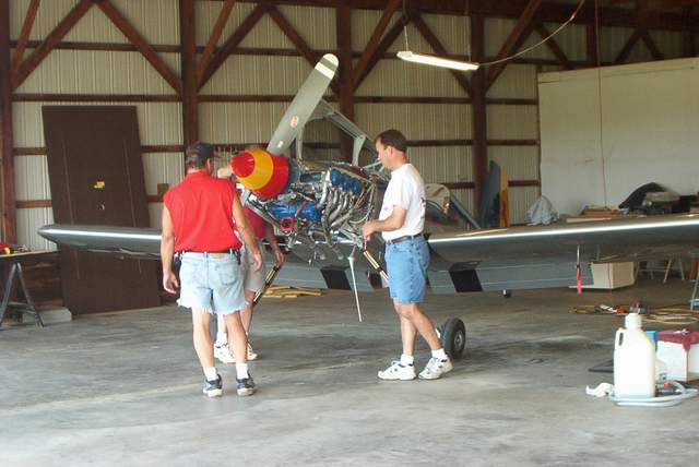 Several sets of eyes look over the engine prior to the first start.
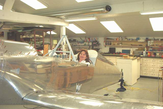
 The wife was on hand to monitor her investments.
 Everything looks ready... except the pilot!
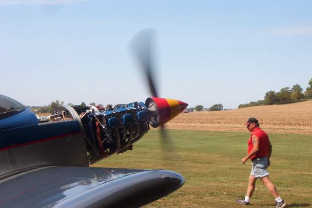 Three blades and VROOM! I was surprised at how quickly she started!
 Mike adjusts the mixture. It's too hard to reach the mixture screw from the
cockpit so get good help!
Mike adjusts the mixture. It's too hard to reach the mixture screw from the
cockpit so get good help!
 As soon as I stomp on a few more bugs, she'll be ready to go.
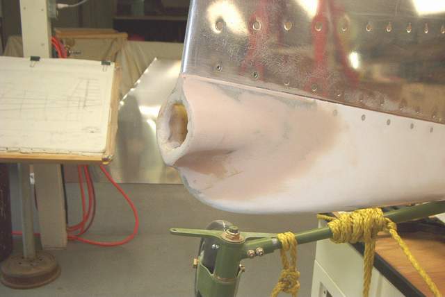
NACA vents:
My vents are located such that the cowl split line, if extended, would cut
through the upper third of the NACA vent. The leading edge of the vent is 3.5
inches from the cowl line, and the vent it self is 4.0 inches long and 2+1/8
high. I angled the vents center line down approximately 2 degrees from level to
better align with the local airflow. I ran the cowl hinge pin out the NACA duct,
rather than out the front of the cowl as is conventionally done. To do this I
had to epoxy in a short length of AL tubing to act as a guide for the pin so
that it will hit the hole in the firewall needed for the pin to pass through. I
used the vans plastic NACA vents, but cut the opening smaller, and it still
flows more than enough. 2 inch SCEET connects to AL eyeball vents in the panel.
The only flow control for the vent air is at the eyeball vents, and this is
working fine. Greg Nelson *end of comment*
Jim Tufts has successfully mounted these vents on the
sides of his F1. Problem is, Jim is not on the 'net to hear these questions! Let's see if
I can recall what I told him:
The fwd edge of the cutout should be 2" aft of the firewall web. Shorten this cutout
by 1" or more in chord (length) -- do not change the outside edge shape. The
centerline of the cutout should be 4" below the top longeron, and aligned with the
waterline of the ship.
Tip: be sure the fwd edge of the inlet cutout has a smooth transition into the floor of
the inlet ramp, or you'll have all sorts of turbulence in the inlet, causing some very
strange airflow patterns & noises. The NACA type inlets are very sensitive to
turbulent flow fwd of the inlet ramp -- watch the skin profile for lumps & bumps etc.
I didn't notice any engine heat coming in thru this setup.
Along this line, be sure the skin joint in front of the lower wing inlet is smooth too.
You may need to remove the tank and massage the TE of the tank skin a bit to get this
right.
I would suggest one inlet & outlet is enough -- you might want to make an additional
provision for air onto your feet or at least into that area. Mark Frederick *end of comment*
To those of you who want better air flow through (hot and cold) the cockpit with smaller systems providing you with greater comfort, you need to stop the battle of inlet air coming from the front of the plane (your design) with that coming from the tail (and to some extent from the wings, rear canopy skirt, flap rod holes, etc.). The RV-4 tail PUMPS!!! and I suspect that the other designs do also.
After 35 hrs. in the back of an RV-4, X-country, that had a single hole in the fire wall (no hoses in cockpit) providing heat evenly to the cockpit (front and back) I wanted to know how it worked so well. Other RV's didn't work this well, including mine. Sleeping under the wing, I spotted a hole in the center of the belly of the tail cone that turned out to be one of those plastic NACA ducts BACKWARDS (located 49" ahead of the back end of the fuselage). WAS this it? I wasn't about to cut up my bird to find out. The owner had purchased the RV-4 and had no idea why it was there. He thought it was part of the design (no hoses to it).
Here is how I improved cockpit comfort: To stop cold air from coming in and freezing certain body parts: 1) I sewed up some boots for the aileron push tubes from light weight synthetic Swede leather (women's garment from the GoodWill provided the material). 2) Sealed the canopy to canopy rails with "P-Strip" from Van's. 3) Sealed the front of the canopy to the cowl boot with the silicone pressed into plastic wrap. 4) Sealed the front right corner of the canopy to canopy rail with a piece of foam wedge. 5) Covered the flap arms with a shaped aluminum panel (this was for safety also). No problem with rear skirts because I don't have them. No stick boots either but maybe one day. The lack of stick boots does allow for airflow under the floorboards but I'm not sure that this is an advantage. All of this sealing improved the situation.
My source of fresh air is a 7/8" hole in the left wing root fairing, plumbed with 1" hose to an instrument panel mounted Wemac(sp) ball. My source of hot air is a standard heat exchanger through a 1.5" valve (Lancair) on the center of the firewall. In the future I will be adding some general purpose cooling air near the rudder pedals with a valve. Right now I am bypassing the heat exchanger in the summer. Before I made the previously mentioned changes, this is what happened. I would open my vents and would receive a blast of air that would then diminish as the cockpit would pressurize. The fight was on between the front air and the tail air. The "front lines" (front lines= that point where the two pressure fronts meet) were at the cockpit. Without stick boots I have plenty of openings front to back under the floor boards. With stick boots I would have to open a 2" (min.) hole in the back of the baggage compartment (in a location where baggage would not block it). The RV-4 has enough of an air flow leak around the back seat to the baggage compartment.
Optimizing the ventilation: 1) Remember that I didn't want to cut a reverse NACA Duct in my RV's belly? It so happens that I have an inspection hole forward of the first tail bulkheads (this was to get at the bolts that hold my tail on. I made up a second cover plate for that hole, cut an 1 1/4" hole in it and made a fiberglass cover for the hole that looks like a rounded over half of a jar lid. Think of it as a reverse scoop. The trailing edge of this device is a 1/2" above the cover plate surface. The rounded over leading edge is a 3/16"radius (from the side it looks like the top half of a wing leading edge) and the purpose is to create a low pressure area over the hole. I haven't sewn a boot for the elevator push tube at that first tail bulkhead yet, but I moved the battle "front lines" back to the tail where the air flow is vented via the device I made up. I now have so much hot air that I can't open the valve but a crack. 2) Seal the tail off with a boot and put a reverse something NACA duct (inset) or low pressure device (outset) forward of the booted bulkhead on the belly or wherever. My proof of concept part is just under the leading edge of the left horizontal stab. (remember that it is also an inspection cover). *end of comment*
There's much discussion about whether air outlets are needed. Some have suggested making boots to seal around the aileron pushtubes and sealing other openings under the floorboards. Who knows? I plan to fly mine before I do any work to enhance the ventilation. Vince *end of comment*
Seat Belts:
I am sure many of you have enjoyed an experience similar to mine while in the midst of building a homebuilt airplane. That experience is getting home late in the afternoon and finding a package from U.P.S. or FedEx, or even the post office. Opening it is like the joy of a child opening a birthday or Christmas gift to find some new item for your airplane. When it is every bit as good as you hoped it would be, your spirit is lifted, and you are RE-encouraged to keep on keepin' on with the project. Another experience that is less often encountered is that of dealing with a supplier who is helpful, and knowledgeable, and really seems interested in helping you find that first experience I described. Such was the case recently when I began shopping for seatbelt/shoulder harness for my Rocket II. After a good deal of shopping, I called Team Simpson of the racing car fame whose business is making flameproof driving suits, helmets, and, of course top quality seatbelts. They call them "restraint systems." (At my age I don't want anything that restrains me! Life is difficult enough as it is!)
Back to the story. I was connected to a young lady named Belenda Seitz. What a joy to encounter her. She was enthusiastic, and energetic, and mostly she was determined to make sure I had a "restraint system" that would satisfy me. She told me what information she would need for me to provide measurement wise, and explained how she thought my system should differ from race car systems. Example, I thought I would have the adjustment straps pull-up from the belts anchor points, but she explained that if I was securing myself in the cockpit, I would need the pulldown adjustments. If I had someone to help me like a pit crew in a race car, the pull-up adjustments would be better. Everything she suggested was completely explained and her questions were very informative to me in order that she could make sure I was going to be properly "restrained." When the order was placed Belenda told me that the crew who would assemble my belts was going home from work in about half an hour, but that she would go to their department, show them the order, and make sure that everything was set for work to begin the next day. You see, the next weekend was the Labor Day Holiday, and Belenda was going to do her best to ship the next day, and assure the delivery of my system by Friday. I have never had such incredible service! I am sending this e-mail to her supervisor, and am asking him to not be to hard on her for spending so much time on one order. She was phenomenal! The next day an e-mail arrived from Belenda assuring me that the order had shipped, and that if U.P.S. did their job my "system" would arrive on Friday. Sure enough, there it was, and WOW, what a gorgeous set of belts. Belenda if we could just clone you and have you work at the other aircraft parts houses we patronize.............., but alas, Simpson has you. Thank you seems inappropriate to convey my sentiments. So a thousand thank you's!
Now guys, (and gals), if you are shopping for a "system" for your Rocket, or RV-4/8 just call Team Simpson at 800-654-7223, ask for extension 121, tell Belenda that you want exactly the same thing that Les Featherston ordered, and you will be absolutely delighted. What I got was the Platinum Series in 2" polyester webbing with the CamLock buckle. I got a 5 point system for the front seat, and a 4 point for the rear. Everything was exactly the correct length, and the attachments were perfect. The materials are beautiful, and the CamLock is really, really nice. And now the creme de la creme! Simpson is offering a 20% discount on their belts till the end of September, IF you send them the tags from an old seatbelt/shoulder harness that you have in that box somewhere in the hangar. Get creative, and you can get that 20% off. Most of all dealing with Belenda, and Simpson was one of the most pleasant experiences that I have had in all the years of building "the beast"! Les
Les used the camlock buckle which is difficult to latch. Maybe some lubricant would help. Based on this, you might want to use the standard (and cheaper) buckle. Vince
I also used the same Simpson belts that Les has, though with the standard buckle. They are the best bang for the buck you can buy. Vince
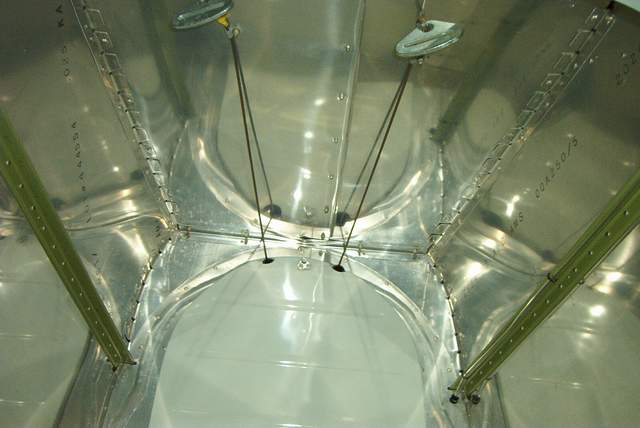
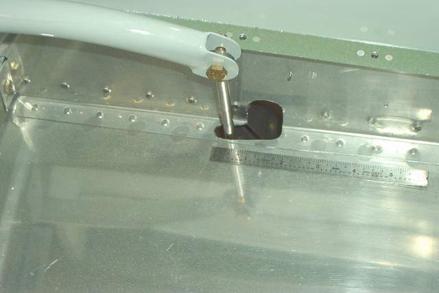
Elevator trim cables
 THIS DIDN'T WORK! But I left the info here so you don't do the same thing!
The vernier cable simply has too much springiness built into it. It would
not hold the trim tab firmly... probably firm enough, but I don't want it moving
unless I move it!
THIS DIDN'T WORK! But I left the info here so you don't do the same thing!
The vernier cable simply has too much springiness built into it. It would
not hold the trim tab firmly... probably firm enough, but I don't want it moving
unless I move it!
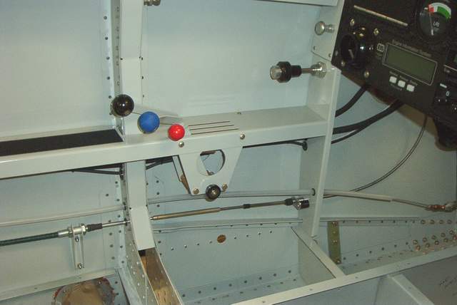
6-02-04: I had long ago installed a standard Van's RV-4 manual type elevator trim cable. The RV-4 cable is exactly the wrong length for what I needed now. I didn't really have enough room to mount the normal trim lever behind the throttle quadrant. Hmm, what to do? THIS DIDN'T WORK!
What I did was to mount a vernier throttle control on the bulkhead in front of the throttle quadrant. You can see the vernier cable looping back to intercept the Van's cable. THIS DIDN'T WORK!
Attaching the two 10-32 male cables ends required a properly sized and tapped piece of aluminum rod. The length of the rod was determined by where the cables ends would conveniently mount. Installing the rod was problematic since the entire vernier cable had to be turned to screw the end in. This has to be done with the cable installed, you can't do it out on the bench. No huge problem though. I used Locktite on the threads since a jam nut would interfere with the # 4 bulkhead. THIS DIDN'T WORK!
You can see the bracket holding the Van's cable, made from an old aileron bracket. THIS DIDN'T WORK!
The vernier cable is held by a clip that bolts to the bulkhead. This clip can be spaced forward or aft with washers to adjust the "throw" of the vernier. THIS DIDN'T WORK!
It seems to work well. The fine adjustment of the vernier knob will hopefully allow easy high speed adjustments, while low speed adjustments can be made by pushing the button and moving the knob. Yes, I know that Van's takes the button off of his vernier knobs to prevent accidental "bumps". For now, I'm leaving mine as is. THIS DIDN'T WORK!
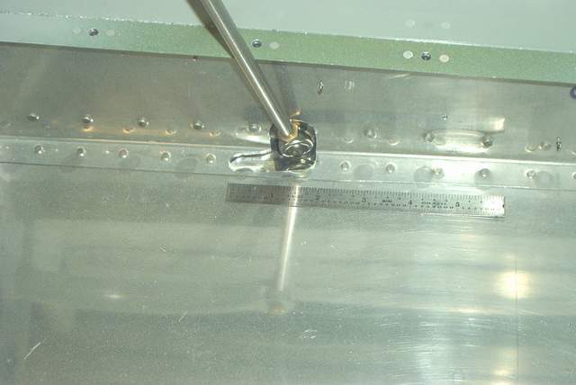
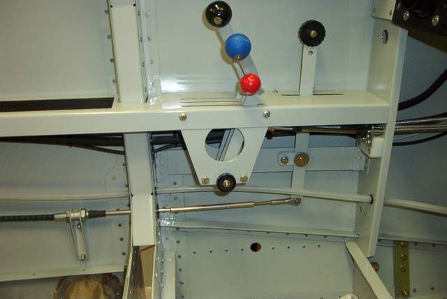 8-19-04: This is much the same as Van's uses. The
elevator trim replaces the futile attempt to use a vernier cable that had much
too much play in it. You can see the threaded rod that connects the lever
to the much too short RV-4 trim cable. If you look closely, you can also
see the structure that had to be added to support the trim lever. It had
to be shoehorned in behind the throttle quadrant, but it really wasn't too
difficult.
8-19-04: This is much the same as Van's uses. The
elevator trim replaces the futile attempt to use a vernier cable that had much
too much play in it. You can see the threaded rod that connects the lever
to the much too short RV-4 trim cable. If you look closely, you can also
see the structure that had to be added to support the trim lever. It had
to be shoehorned in behind the throttle quadrant, but it really wasn't too
difficult.
Be sure to set the travel for more nose up trim than nose down.
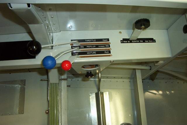
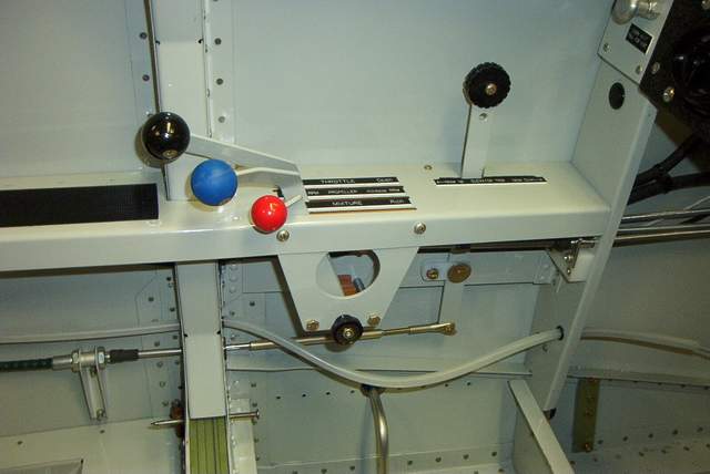 9-10-04: Throttle quadrant and elevator trim stuff.
The throttle levers are bent (cut actually) in a banana shape so that I can
easily reach them with my arm on the arm rest. Lazy? You bet!
9-10-04: Throttle quadrant and elevator trim stuff.
The throttle levers are bent (cut actually) in a banana shape so that I can
easily reach them with my arm on the arm rest. Lazy? You bet!
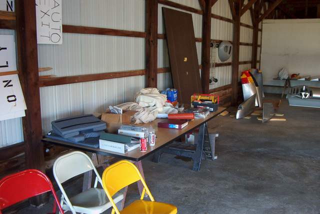
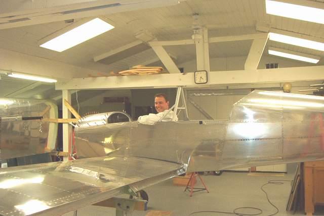
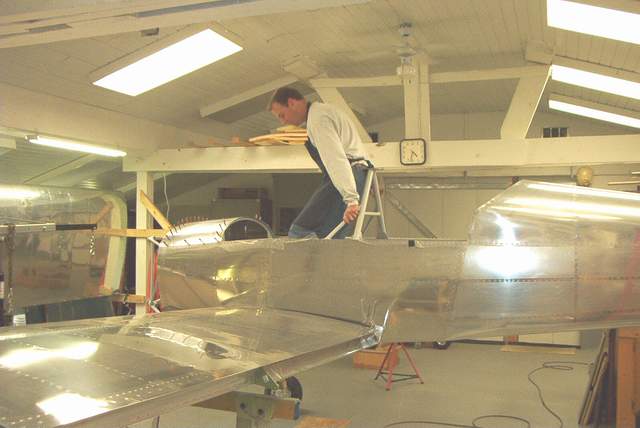
 5-11-04: Tom Martin
posted to Chip's site a picture of a labor intensive scaffold that he built.
Being rather lazy, I decided to use this shelf unit bought from Home Depot for
about $100. It is fully adjustable for height and can be used as seen, or
raised for use when the wings are on. It really works well, although it squeaks
a little when you move around on it, which distracts me from listening to the
Bose stereo in the shop. Wwwaaaaaah!
5-11-04: Tom Martin
posted to Chip's site a picture of a labor intensive scaffold that he built.
Being rather lazy, I decided to use this shelf unit bought from Home Depot for
about $100. It is fully adjustable for height and can be used as seen, or
raised for use when the wings are on. It really works well, although it squeaks
a little when you move around on it, which distracts me from listening to the
Bose stereo in the shop. Wwwaaaaaah!
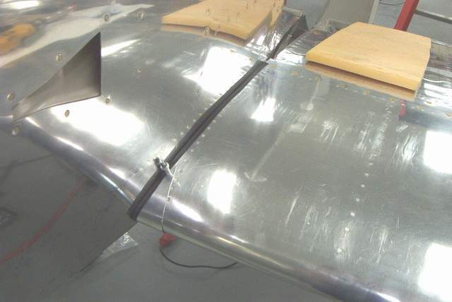
Flap pushrod seals:
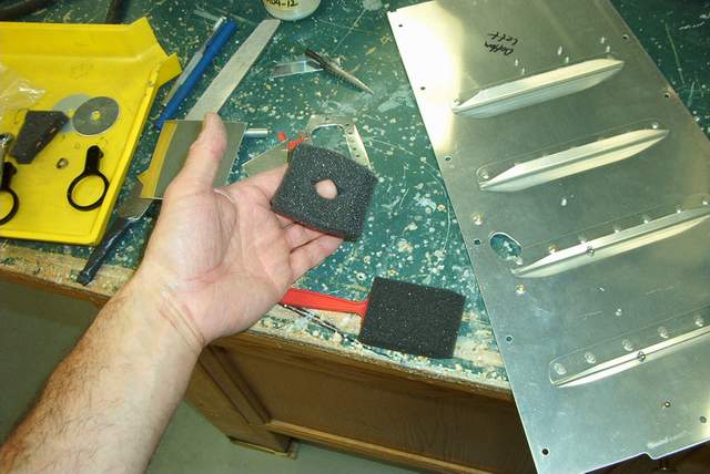
In the lower right corner you can see a hole which I melted through the foam with a soldering iron. When you install the floorboard, a screw goes through that hole. The foam scrunches down nearly flat, as you can see, and does not cause any fitting problems even though it is between the floorboard and angle on the fuselage.
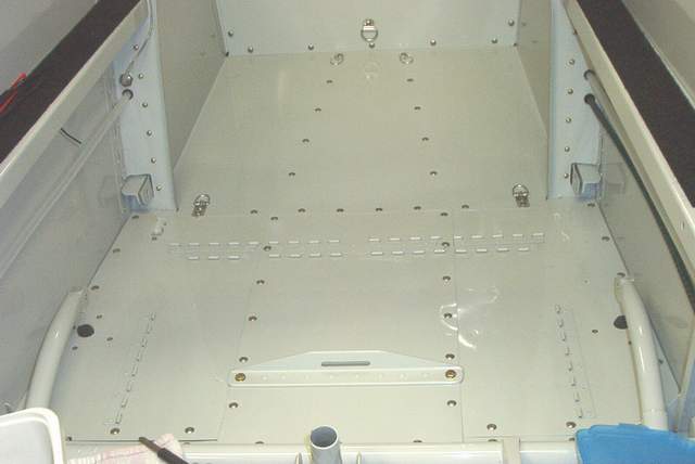
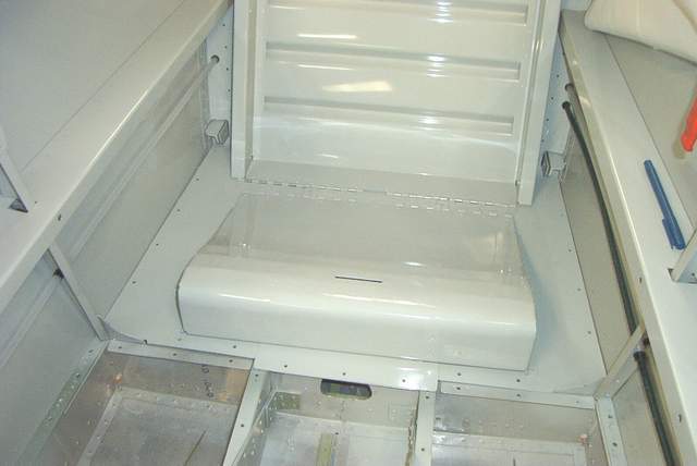
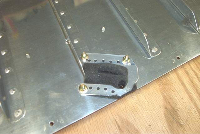
You can also see the piano hinges everywhere. The aft (top) one holds the rear seat back. The others hold the rear seat pan, a wedge shaped, slightly curved aluminum masterpiece that fits my butt so well that I barely need a pad. The crotch strap fitting is hidden by the seat pan when the pan is in place.
That little blur in the upper left hand corner of the middle photo is where the rear seat heat plugs in. The seat heat cost next to nothing and now the wife says she's looking forward to flying. She hates cold weather.... anything less than 75 degrees.
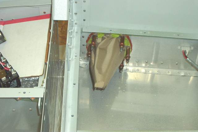
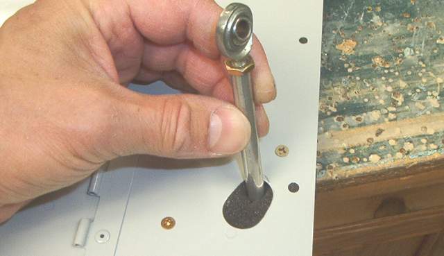
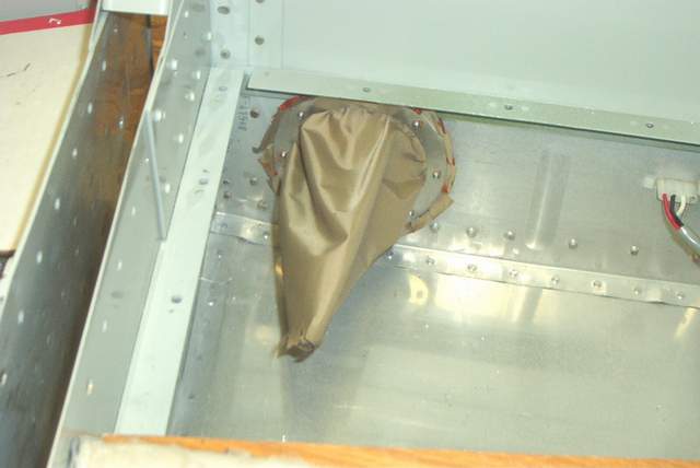 5-11-08: An RV-8 builder gave me these nylon aileron
pushtube booties to keep the drafts out of the cockpit. Installation was a
simple aluminum ring, some RTV, and a few LP4-3 rivets.
5-11-08: An RV-8 builder gave me these nylon aileron
pushtube booties to keep the drafts out of the cockpit. Installation was a
simple aluminum ring, some RTV, and a few LP4-3 rivets.
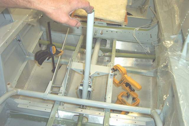
Wing installation:
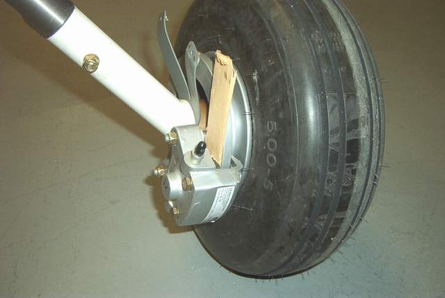 4-21-03: Here's a way to chock the wheels while
putting the wings on. A wood wedge tapped between the disc and pad will do
it.
4-21-03: Here's a way to chock the wheels while
putting the wings on. A wood wedge tapped between the disc and pad will do
it.
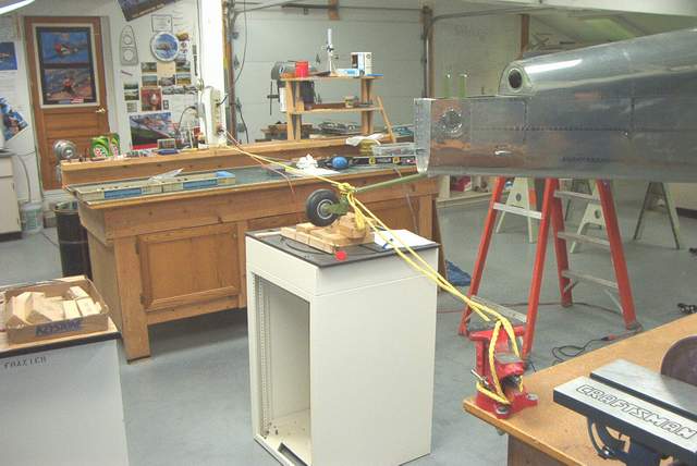 While fitting the wings, the tail needs to be up in the air about 3 1/2'.
Tie the dang tail so it won't move around while you're pushing the wings in.
You'll be sorry if you don't.
While fitting the wings, the tail needs to be up in the air about 3 1/2'.
Tie the dang tail so it won't move around while you're pushing the wings in.
You'll be sorry if you don't.
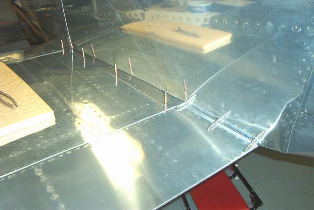
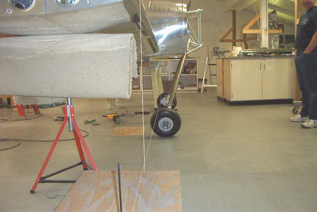 My inboard skins needed a little trimming which required several wing insertions
and retractions to get the trim right. After trimming and sticking
the wings in the holes, you adjust the sweep using a few plumb bobs. Easy
enough. Then measure to the tailspring and square the wings with the
fuselage. It's easy enough to get everything within 1/16" or so.
My inboard skins needed a little trimming which required several wing insertions
and retractions to get the trim right. After trimming and sticking
the wings in the holes, you adjust the sweep using a few plumb bobs. Easy
enough. Then measure to the tailspring and square the wings with the
fuselage. It's easy enough to get everything within 1/16" or so.
I didn't take a picture of the incidence setting operations. Dang. The data I have from Mark tells me to set the rear spar height 2.95" lower than the main spar when the fuselage is level. Due to edge distance requirements of the rear spar bars, the required distance was about 3.2" OH NO!!! It's a 1/4" off. So what? It's no big deal. Just set the HS accordingly. Here's one way: Level the wings using the 2.95" dimension. Ignore the longerons 'cuz they aren't level anymore. Set the incidence on the HS using a 1/8" spacer on the front spar and a 13/32" spacer on the rear spar. I know you guys who measure stuff to the nearest 0.001" are puking right now. Just remember, we're not going to Mars here. Just build it. If needed you can shim the engine thrust line or shim the tail a bit after you fly. I'll bet you a case of beer that you'll never notice. Besides, this is how Van himself told me to do it on my RV-4 which went 200 mph on a measly 150 hp.
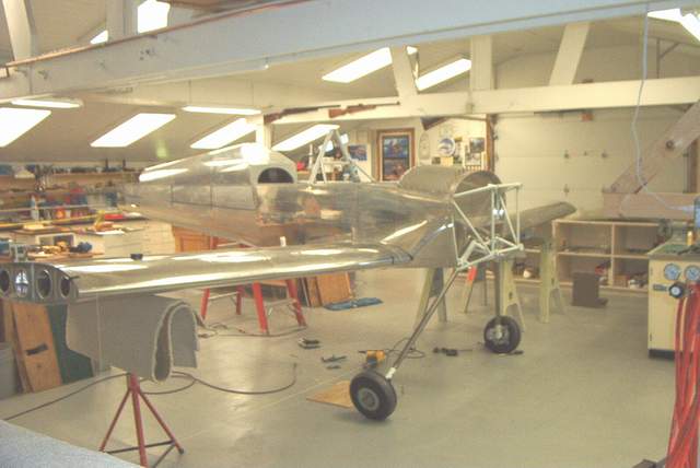
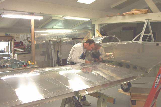
 Get
good help. John is excellent help, as plainly seen here.
Get
good help. John is excellent help, as plainly seen here.
 FULL THROTTLE!!!!!!
Tail installation:
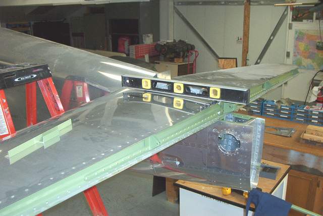 Setting the tail incidence.
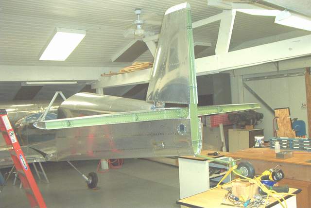 5-5-03: Putting on the VS
 Rudder stops. When you install these, make sure that the rudder cables
don't rub on them. I had to move the stops as the first set rubbed the
cable fitting. Doh!
Rudder stops. When you install these, make sure that the rudder cables
don't rub on them. I had to move the stops as the first set rubbed the
cable fitting. Doh!
Notice how the trimmed out area for the rudder bottom is sort of a misshapen notch... but that's what was needed for a reasonably tight fit when the rudder swings. More length on the fuselage skins would be good here. I thought I would have needed to trim all the way to the main longeron... but no. And I left the skins hanging over waaaaay longer than the RV-4 plans would indicate.
 The VS/HS front spar attach. The RV-4 attachment is completely different
that what the F-1 uses. I cobbled together an attachment similar to the
F-1 parts by adding a doubler to the rear face of the HS. Not shown in the
picture are the HS forward spar doubler strips (sorta like the main spar bars).
I added a little extra in that area since someone is always pushing on the
leading edge of the HS when ground handling the plane.
The VS/HS front spar attach. The RV-4 attachment is completely different
that what the F-1 uses. I cobbled together an attachment similar to the
F-1 parts by adding a doubler to the rear face of the HS. Not shown in the
picture are the HS forward spar doubler strips (sorta like the main spar bars).
I added a little extra in that area since someone is always pushing on the
leading edge of the HS when ground handling the plane.
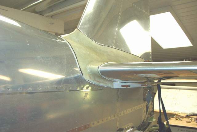
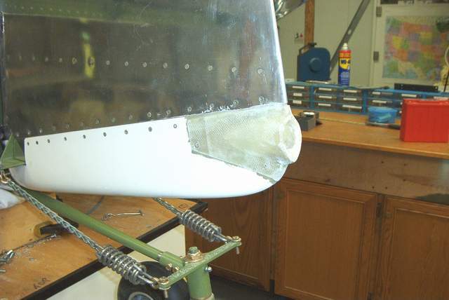
Fairing fabrication:
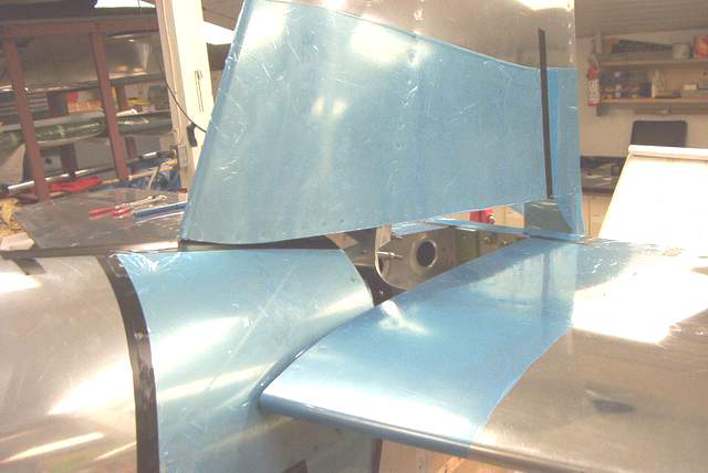 5-14-03: Monday night I prepped the tail for the horrible mess to come by
covering all of the exposed aluminum. The guy building an RV-7 in my shop
will notice that somebody stole a bunch of that protective plastic crap off of
his wing panel. I used it to cover my tail. Worked great, epoxy peels off
of it fairly easily, and the price was right. I did use a little black
tape around the edges to seal the plastic down.
5-14-03: Monday night I prepped the tail for the horrible mess to come by
covering all of the exposed aluminum. The guy building an RV-7 in my shop
will notice that somebody stole a bunch of that protective plastic crap off of
his wing panel. I used it to cover my tail. Worked great, epoxy peels off
of it fairly easily, and the price was right. I did use a little black
tape around the edges to seal the plastic down.
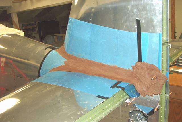 Yesterday I brought home about 15# of modeling clay that I "borrowed" from the
art department (they're on summer break). I smooshed it all over the tail
intersection until it looked about right. Actually you don't really look
at it so much as you feel for lumps. Heck any good body shop guy could do
this in no time. For that matter, Ray Charles could too.
Yesterday I brought home about 15# of modeling clay that I "borrowed" from the
art department (they're on summer break). I smooshed it all over the tail
intersection until it looked about right. Actually you don't really look
at it so much as you feel for lumps. Heck any good body shop guy could do
this in no time. For that matter, Ray Charles could too.
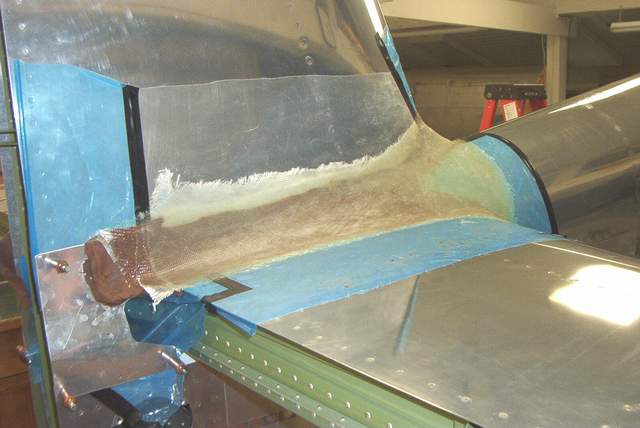
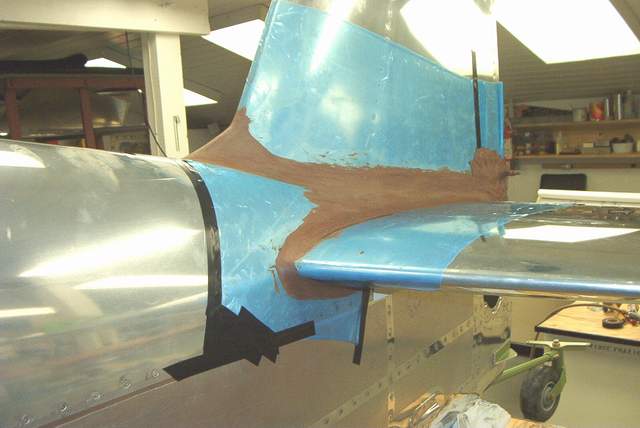
 So, after I spent an hour molding the sticky stuff, it was time to start with
the really yucky stuff. No, I'll never win any awards for fiberglass work.
The local Glassygofast builder tells me that the ratio (by weight) of glass to
resin should be 2:1. My ratio is more like 1:1 or 1:2. Doh! I can't
believe that you can actually build an entire airplane out of that stuff.
So, after I spent an hour molding the sticky stuff, it was time to start with
the really yucky stuff. No, I'll never win any awards for fiberglass work.
The local Glassygofast builder tells me that the ratio (by weight) of glass to
resin should be 2:1. My ratio is more like 1:1 or 1:2. Doh! I can't
believe that you can actually build an entire airplane out of that stuff.
After a quick double checking to make sure that everything was ready, the tail is covered, and the glass is cut, it was time to glove up... double glove actually. A few thousand pumps of the West cans later and VOILA (drum roll).... well, I'll be dipped... a suitable looking fairing had appeared where before there were only lumps of clay!
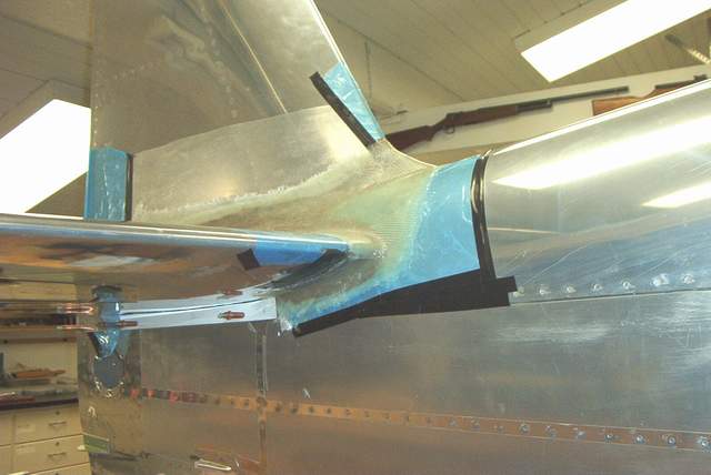
 And after trimming it with the band saw (with the old blade). Next I'll
proceed to the really fun part... hours and hours of sanding and filling.
ACK!
And after trimming it with the band saw (with the old blade). Next I'll
proceed to the really fun part... hours and hours of sanding and filling.
ACK!
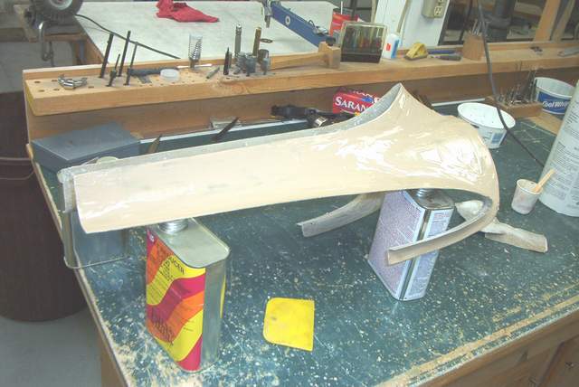 Yummy. This piece was "iced" using West System 410 filler. Looks
like cake frosting.
Yummy. This piece was "iced" using West System 410 filler. Looks
like cake frosting.
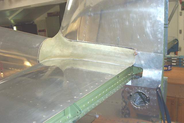
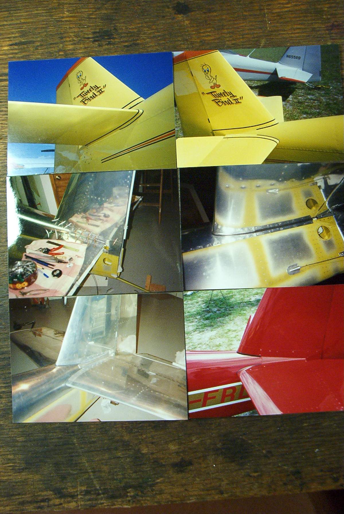 You can also make aluminum tail fairings. They don't warp and they are
cheap. I made mine by taking cardboard and making a rough template.
A few ruined pieces of aluminum later and I had a nice fairing as shown in the
unpainted parts in the photo.
You can also make aluminum tail fairings. They don't warp and they are
cheap. I made mine by taking cardboard and making a rough template.
A few ruined pieces of aluminum later and I had a nice fairing as shown in the
unpainted parts in the photo.
Sorry for the poor quality of the photo... it's a digital photo of the paper photos that I had in my scrapbook.
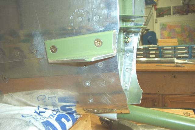
Tank Support Brackets:
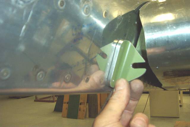
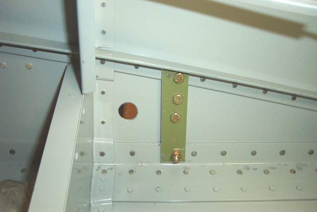
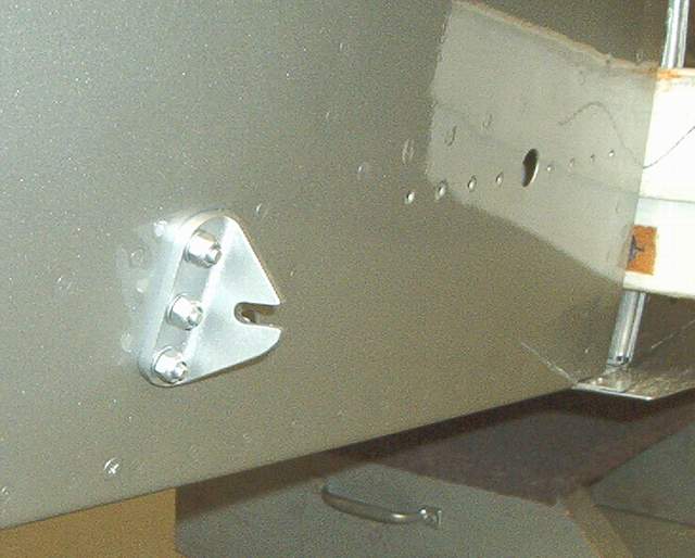
6-18-03: I didn't like the tank support angle that sticks out near the lower front wing root. So, I hid mine by putting a doubler inside the fuselage and bolting a shorter angle outside. In the picture I'm holding it outside of the area where it goes. When installed it is hidden by the tank skin.
The interior doubler is a piece of angle that connects the lower longeron with the upper (diagonal) brace. I used an 1/8" shim to fill the gap as needed.
The exterior angle is the usual part, except that the protruding leg is cut off.
The parts are bolted together at the upper brace (as usual) and in the middle of the whole shebang. All is hidden from view on the outside by my nice flat wrapped fairing.
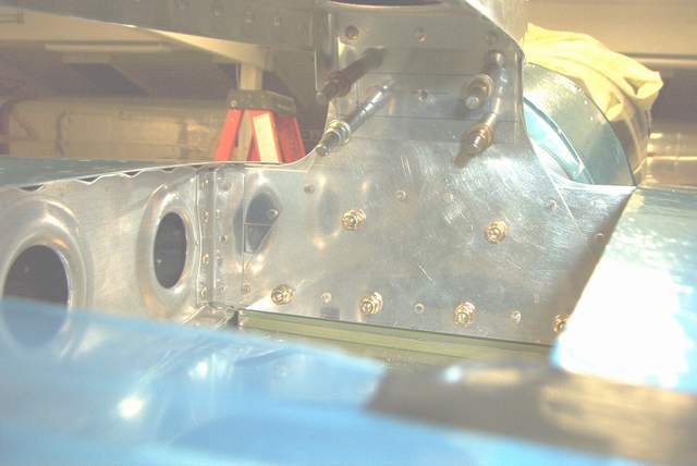
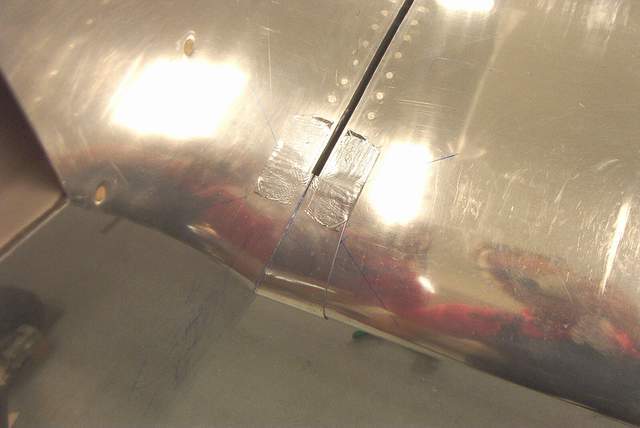
Wing Fairings:
6-18-03: I made flat wrapped aluminum wing root fairings because they are cheap, light, easy to make, and they're NOT made from fiberglass. Dave Anders uses flat fairings on his super fast RV-4. That's enough to make me assume that there isn't any speed penalty versus the big fiberglass fairings, although the FG ones do look nice.
As you can see in the pictures below, my tank flange is VERY close to the fuselage skin. That is one of the SNAFU's of combining the F-1 fuselage with the HR wings. No big deal, but another 1/2" and I'd have been making a new tank root.
Some U shaped rubber finishes off the flat fairing edge very nicely.
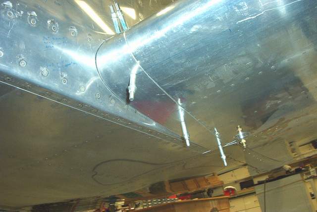
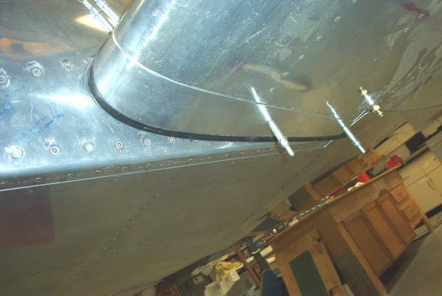
Rudder cables and tailwheel links installation:
6-18-03: The photo above shows the fiberglass tail light fairing as added to the Van's part. Also shown are the cable shackles that I like to use instead of those crappy teardrop shaped wires that Van's provides. The tear drop shaped wires can come off.
6-08-03: This might not be exactly correct for those using an F-1 tail, but my RV-4 rudder swings just under 2 1/4" from neutral to the stop when I measure the movement of the cable. I installed these things yesterday so it's still fresh in my mind. So, that would be about 4 1/2" total travel.
I had to make my own rudder cables since I have a hybrid. I ran the entire rudder cable through some polyethylene tubing, same as I did on my RV-4 years ago. The tubing makes it a snap to feed the cable through the fuselage, but you do have to install your own cable eyes on one end. I put mine up front and have the usual factory swaged fitting on the aft end.
The tubing should keep the cable from wearing a groove in the snap bushings for a loooooong time. I don't get any of that "sawing" noise that some rudder cables make when moved.
When installing the adjustable links between the cable and the pedals, I left about 1/2" of space between the firewall and the depressed pedal. When I stomp on the pedal the slack in the cable eats up that 1/2" but the pedal doesn't hit the firewall. I also cut off the lower forward corners of my (Van's supplied) rudder arms so that I had a bit more legroom.
YMMV, remember I have a hybrid RV/Harmon/F-1 and none of my parts like each other! Vince
Flap installation:
I have the flaps installed and the flap actuating rod holes cut as shown. I like the manual flaps... cheap, light, and reliable. You can see the flap handle in the first picture. It is straight, not S-shaped like the RV-4 handle. You can get away with this since the Rocket has considerably more room that the RV-4. It's a worthwhile mod since it will make the flaps easier to latch. Any RV-4 (with manual flaps) pilot will know what I mean.
Return to the homepage:
http://www.vincesrocket.com/
Last updated: 09/01/06
CAUTION: This web site is not a publication of, nor approved by, Harmon LLC, Team Rocket, Van's Aircraft or any other person or entity listed herein, except me. Be advised that I am a blithering idiot with neither brains nor money and my advice is not to be trusted. So there. You have been warned! Vince