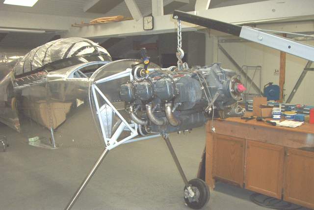
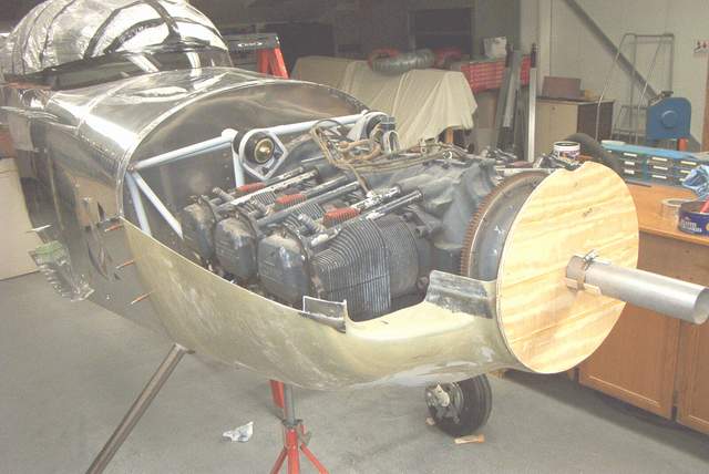
 7-25-03: First, hang the engine. Thankfully this
isn't nearly as difficult as some 4 banger Lycomings. Be sure to pay
attention to where you put the dense biscuits. Read the Barry mount directions if
you're confused by this statement.
7-25-03: First, hang the engine. Thankfully this
isn't nearly as difficult as some 4 banger Lycomings. Be sure to pay
attention to where you put the dense biscuits. Read the Barry mount directions if
you're confused by this statement.Cowling and Airbox
Cowling Installation:
7-25-03: First, hang the engine. Thankfully this
isn't nearly as difficult as some 4 banger Lycomings. Be sure to pay
attention to where you put the dense biscuits. Read the Barry mount directions if
you're confused by this statement.
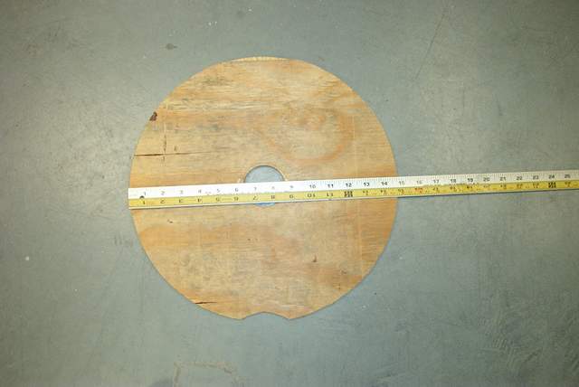
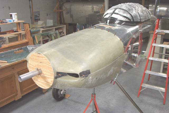
 7-25-03: A tool to simulate the position of the prop spinner is
necessary to accurately install the cowling. You can make one from an old prop
spacer, a piece of pipe, and a 15" disc of wood. Don't get all hung up on
measuring to the nearest 0.001" here. Close is good enough. In other
words... "No, you don't need to turn the 15" disc on a lathe. A band saw
cutout is fine." You'll see what I mean when you get started.
7-25-03: A tool to simulate the position of the prop spinner is
necessary to accurately install the cowling. You can make one from an old prop
spacer, a piece of pipe, and a 15" disc of wood. Don't get all hung up on
measuring to the nearest 0.001" here. Close is good enough. In other
words... "No, you don't need to turn the 15" disc on a lathe. A band saw
cutout is fine." You'll see what I mean when you get started.
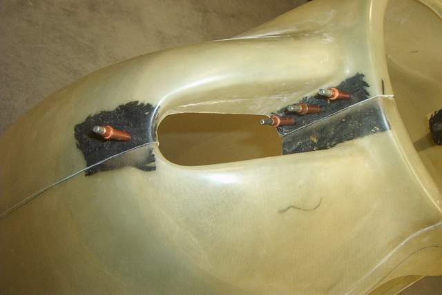
You could even use a block of wood instead of the old prop spacer. Just egg out the holes as needed until the 15" disc tracks properly when you rotate the crankshaft.
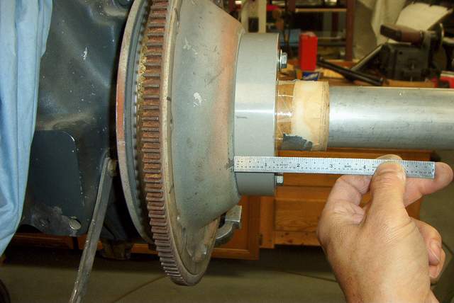
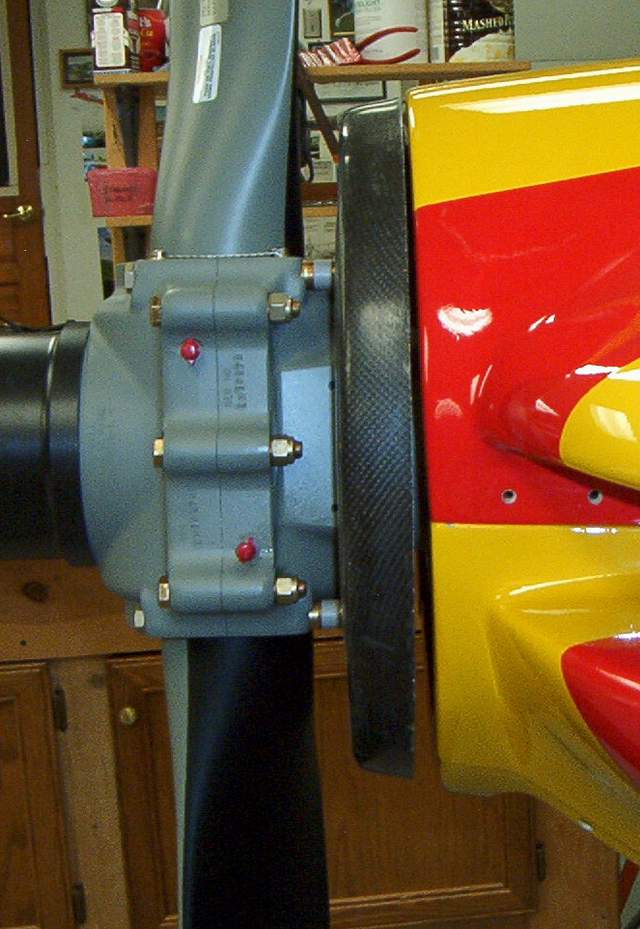
You'll need to install your spinner backplate on your prop and double check the measurements from the aft face of the prop hub to the aft face of the spinner (this is the same measurement as from the front face of the starter ring to the aft face of the spinner). You can do this on your workbench. This will determine where you place the wooden disc on your cowling tool. After all, you don't want the cowling hitting the spinner!
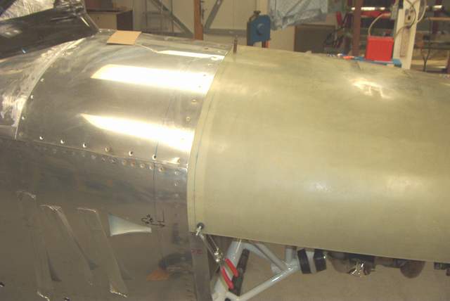
My aft face of the prop hub to spinner backplate measurement came out to about 3". I'll need to shave off about 1/4" from the spacer between the prop spacer and the 15" disc. This will set the front face of the cowling aft a bit. This is how you set the spacing between the cowling and the spinner. See the photo below.
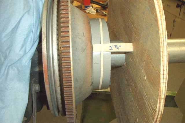 8-8-2003: Make some temporary spacers and double
check your measurements! Mine were 2.75". This should give me a 1/4" gap
between the spinner and cowl.
8-8-2003: Make some temporary spacers and double
check your measurements! Mine were 2.75". This should give me a 1/4" gap
between the spinner and cowl.
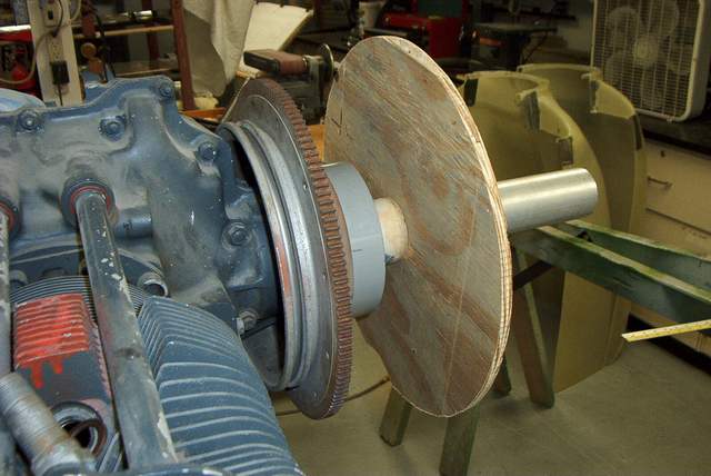
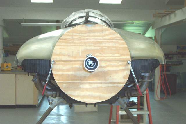
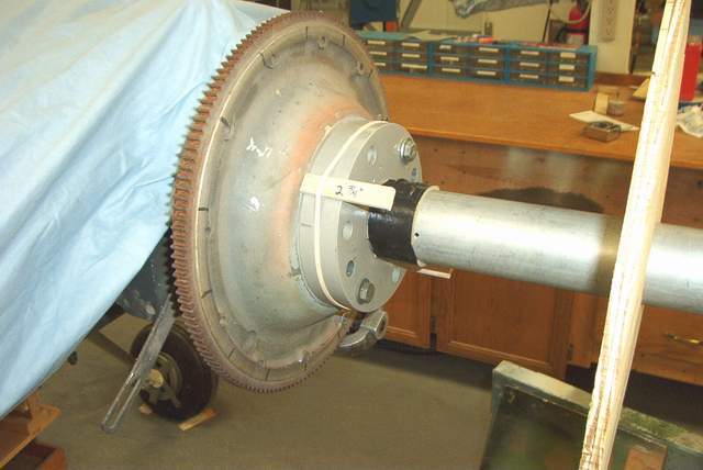 The tube from an old roll of tape can be cut up to make a nice firm spacer.
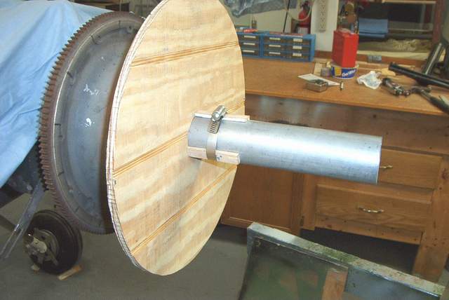 Then add the 15" wooden disc and clamp it against the spacers with a few small
wooden blocks and a hose clamp. Give the crankshaft a spin to make sure
there isn't excessive wobble. A small amount of wobble is OK since you are
only using this fixture to set the distance from the front face of the cowl to
the firewall. In other words, your not setting the spinner in place so
don't fret about a little wobble too much here.
Then add the 15" wooden disc and clamp it against the spacers with a few small
wooden blocks and a hose clamp. Give the crankshaft a spin to make sure
there isn't excessive wobble. A small amount of wobble is OK since you are
only using this fixture to set the distance from the front face of the cowl to
the firewall. In other words, your not setting the spinner in place so
don't fret about a little wobble too much here.
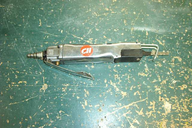 SHOP TIP: I bought an air. saw, more or less an air
powered saber saw. The blade really moves fast. It's the greatest
thing for cutting fiberglass. Twice as fast and very little dust compared
to a cutoff wheel.
SHOP TIP: I bought an air. saw, more or less an air
powered saber saw. The blade really moves fast. It's the greatest
thing for cutting fiberglass. Twice as fast and very little dust compared
to a cutoff wheel.
 With the cowl halves setting on the floor, make your first rough trims.
Trim lines are molded in, but leave a little extra for fudge factor. You
can trim more off later. Get the front of the cowl trimmed enough so you
can put a few clecoes in. Make sure that the spinner opening matches your
spinner, i.e. make it match the 15" wooden disc!!! You want a round hole,
not an oval!
With the cowl halves setting on the floor, make your first rough trims.
Trim lines are molded in, but leave a little extra for fudge factor. You
can trim more off later. Get the front of the cowl trimmed enough so you
can put a few clecoes in. Make sure that the spinner opening matches your
spinner, i.e. make it match the 15" wooden disc!!! You want a round hole,
not an oval!
It is probably safe to trim the side of the cowls fairly close to the trim line, but I'd wait until later to do the final trimming so you can have some vertical adjustment of the bottom cowl. That way it will fit nice and snug against the belly near the gear legs.
 Clamp the top cowl in place. (Wow! You've just put a big part of the plane
on and it sure looks good, doesn't it?)
Clamp the top cowl in place. (Wow! You've just put a big part of the plane
on and it sure looks good, doesn't it?)
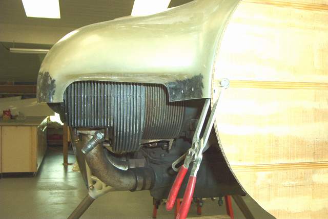
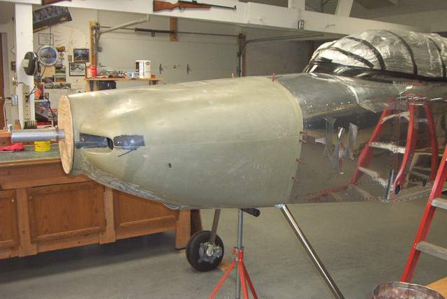
 Set the top edge of the cowl a smidge lower than your wooden disc to allow for
engine sag later. The air inlets are aligned by eyeballing the casting
lines on the cylinders. Then if you're still concerned you can level the
plane side to side and check the inlets by measuring up to the inlets (assuming
that your floor is level). Both of my inlets were about 52.75" from the
floor (depends on how high the tail is setting). It just helps confirm
that your eyes aren't playing tricks on you to double check this way.
Set the top edge of the cowl a smidge lower than your wooden disc to allow for
engine sag later. The air inlets are aligned by eyeballing the casting
lines on the cylinders. Then if you're still concerned you can level the
plane side to side and check the inlets by measuring up to the inlets (assuming
that your floor is level). Both of my inlets were about 52.75" from the
floor (depends on how high the tail is setting). It just helps confirm
that your eyes aren't playing tricks on you to double check this way.
 Drill a few cleco holes in the wood and put a big strip of duct tape on the aft
end of the cowl to make sure nothing moves around.
Drill a few cleco holes in the wood and put a big strip of duct tape on the aft
end of the cowl to make sure nothing moves around.
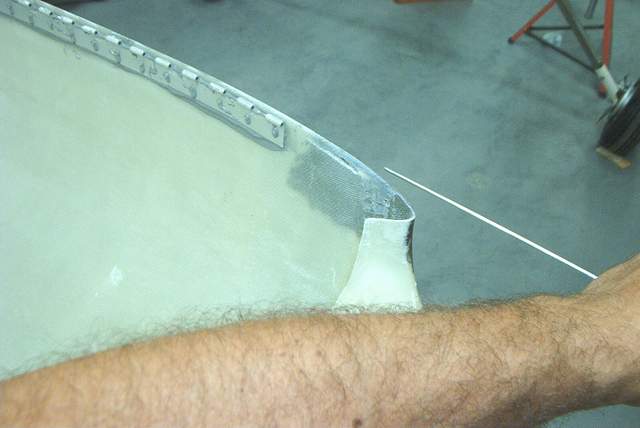
 Make a few marks so that you can tell if anything moves. While you're
making marks, carefully draw a line parallel too and 3" aft of the edge where
the cowl and side skin will meet.
Make a few marks so that you can tell if anything moves. While you're
making marks, carefully draw a line parallel too and 3" aft of the edge where
the cowl and side skin will meet.
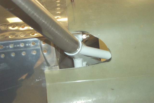
 Hold the bottom cowl up and guesstimate where the gear leg cutout will go.
Use your air saw to hack out a U-shaped hole about 2.5" wide by 5"deep (or
whatever you deem appropriate). When you get the gear leg openings big
enough, install the lower cowling half and cleco the cowl halves together at the front. You might need
something to support the rear of the bottom cowl. An adjustable roller
stand like you use with a table saw works well.
Hold the bottom cowl up and guesstimate where the gear leg cutout will go.
Use your air saw to hack out a U-shaped hole about 2.5" wide by 5"deep (or
whatever you deem appropriate). When you get the gear leg openings big
enough, install the lower cowling half and cleco the cowl halves together at the front. You might need
something to support the rear of the bottom cowl. An adjustable roller
stand like you use with a table saw works well.
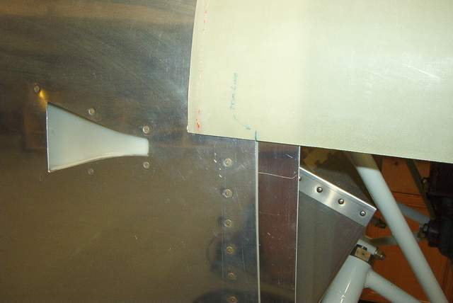
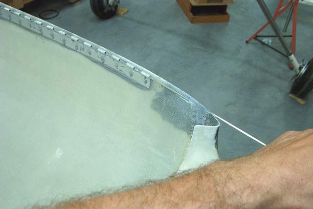
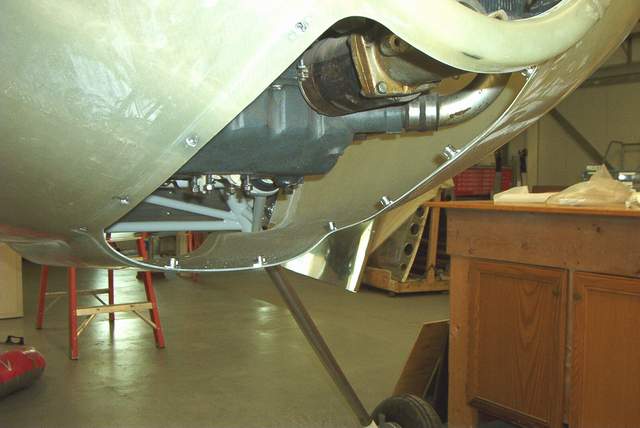
 This picture is a bit out of order because the side skins have been
trimmed off, but it does show the gear leg cutout nicely.
This picture is a bit out of order because the side skins have been
trimmed off, but it does show the gear leg cutout nicely.
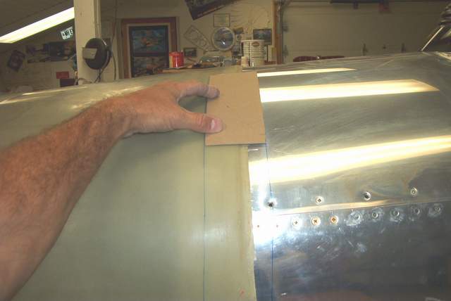 Using the line you drew earlier 3" behind the cowl/skin intersection, transfer
the intersection line onto the cowl. Here I am using a 3" wide piece of
shoebox cardboard as a straightedge.
Using the line you drew earlier 3" behind the cowl/skin intersection, transfer
the intersection line onto the cowl. Here I am using a 3" wide piece of
shoebox cardboard as a straightedge.
 Trim along the line and reinstall the top cowl. Measure carefully where
your firewall flange to cowling fasteners will be and drill a few holes along the aft edge. Put
in a few clecoes. Recheck that nothing has moved as you proceed.
Trim along the line and reinstall the top cowl. Measure carefully where
your firewall flange to cowling fasteners will be and drill a few holes along the aft edge. Put
in a few clecoes. Recheck that nothing has moved as you proceed.
 Put the bottom cowl in position. Using the line you drew earlier 3" behind
the cowl/skin intersection, transfer the intersection line onto the bottom cowl.
Remove the bottom cowl and trim along the line. Reinstall the bottom cowl.
Put the bottom cowl in position. Using the line you drew earlier 3" behind
the cowl/skin intersection, transfer the intersection line onto the bottom cowl.
Remove the bottom cowl and trim along the line. Reinstall the bottom cowl.
 Carefully mark and drill for the aft fasteners. Don't forget to leave some space
for the gear leg intersection fairing fasteners. Install a few clecoes.
Carefully mark and drill for the aft fasteners. Don't forget to leave some space
for the gear leg intersection fairing fasteners. Install a few clecoes.
 Reinstall both halves of the cowling. You should have the firewall flange
fastener spacing laid out and drilled by now. Most use screws and
nutplates on the firewall flange, but I have Skybolt camlock fasteners to use.
More about them later.
Reinstall both halves of the cowling. You should have the firewall flange
fastener spacing laid out and drilled by now. Most use screws and
nutplates on the firewall flange, but I have Skybolt camlock fasteners to use.
More about them later.
You're ready to do the final trimming of the sides now. Try to get the hinge line in the same spot on both sides. The trim lines molded into my cowl might have misled me into having one side a bit higher than the other. Anyway, get the hinge lines laid out on the side and trim as needed to get a nice straight line. Then you'll be ready to add the hinges.
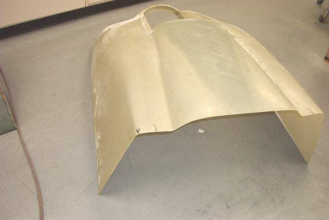
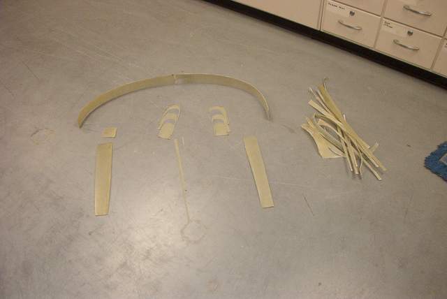 Here's the results of about 6 hours of trimming and fitting. The pile on
the right was from the initial rough trimming of the sides, air scoop, and air
scoop opening. The stuff on the left is, of course, from the actual
fitting of the cowl to the plane.
Here's the results of about 6 hours of trimming and fitting. The pile on
the right was from the initial rough trimming of the sides, air scoop, and air
scoop opening. The stuff on the left is, of course, from the actual
fitting of the cowl to the plane.
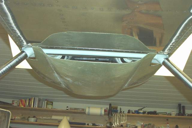 A view of the air outlet during the cowl fitting. Try to get it
fairly even.
A view of the air outlet during the cowl fitting. Try to get it
fairly even.
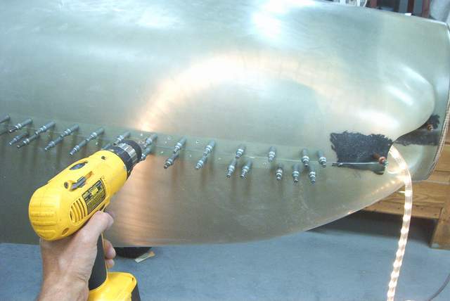 You can put a light inside the cowl so you can drill through the holes
that you predrilled in the hinge. However.... IT CAN BE TRICKY! If
the light isn't DIRECTLY behind the hole you will find that the shadow doesn't
align with the hole and you'll drill the hole in the WRONG spot. Doh!
You can put a light inside the cowl so you can drill through the holes
that you predrilled in the hinge. However.... IT CAN BE TRICKY! If
the light isn't DIRECTLY behind the hole you will find that the shadow doesn't
align with the hole and you'll drill the hole in the WRONG spot. Doh!
I had much better luck by simply looking through the semitransparent fiberglass and viewing the hole with NO lights inside the cowling.
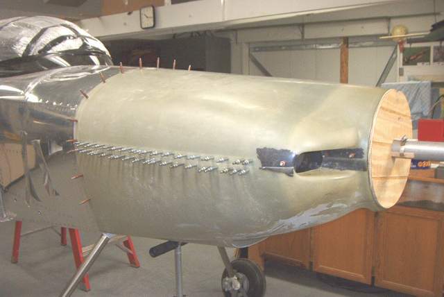 The cowling with drilling completed.
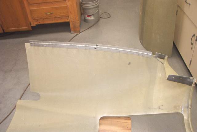
 8-25-03: The hinges are glued on using JB Weld. Yup, JB
Weld... it works very well for this job. The rivet holes are
countersunk then the hinge and cowl are roughed up to promote adhesion.
Soft rivets are used for this job since they don't damage the fiberglass.
8-25-03: The hinges are glued on using JB Weld. Yup, JB
Weld... it works very well for this job. The rivet holes are
countersunk then the hinge and cowl are roughed up to promote adhesion.
Soft rivets are used for this job since they don't damage the fiberglass.
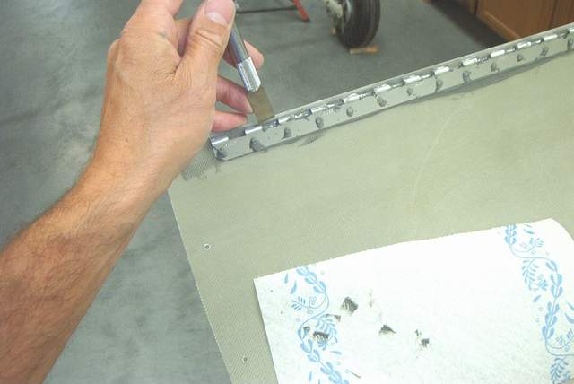 A 1/2" wide Exacto knife is the right tool to clean the excess JB Weld
out of the hinge BEFORE it sets up.
A 1/2" wide Exacto knife is the right tool to clean the excess JB Weld
out of the hinge BEFORE it sets up.
 I like to insert the hinge pins just to make sure that I didn't get a
blob of JB Weld in one of the hinge eyes. Then pull them back out and wipe
them off.
I like to insert the hinge pins just to make sure that I didn't get a
blob of JB Weld in one of the hinge eyes. Then pull them back out and wipe
them off.
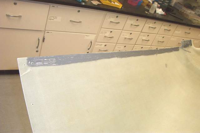
 I used 5 or 6 layers of bid tape to shim the cowl to firewall flange
spacing. Try to get a nice smooth exterior appearance on the joint between
the cowling and the fuselage. Adding the tapes will slightly affect the
way the cowl fits, but it isn't convenient to do this step earlier in the
process. After the tapes have cured, you'll want to reinstall the cowling
and make sure that all of the hole in the firewall flange still line up nicely.
Mine were fine.
I used 5 or 6 layers of bid tape to shim the cowl to firewall flange
spacing. Try to get a nice smooth exterior appearance on the joint between
the cowling and the fuselage. Adding the tapes will slightly affect the
way the cowl fits, but it isn't convenient to do this step earlier in the
process. After the tapes have cured, you'll want to reinstall the cowling
and make sure that all of the hole in the firewall flange still line up nicely.
Mine were fine.
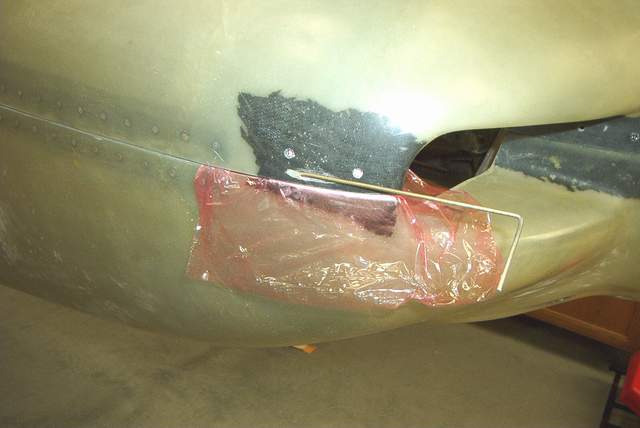
 The oil door is fitted by trimming to approximate size. I
overtrimmed and got the darned thing a bit too small. Well, one good thing
about fiberglass (there aren't many good things) is that you can make the
opening fit the door by using a little flox and epoxy to fill the gaps.
The oil door is fitted by trimming to approximate size. I
overtrimmed and got the darned thing a bit too small. Well, one good thing
about fiberglass (there aren't many good things) is that you can make the
opening fit the door by using a little flox and epoxy to fill the gaps.
The hinge is one that came from one of those grab bags you can get at AirParts. It works very well and there is no exposed hinge to show on the outside. I don't recommend it UNLESS you are planning on using a plenum. I don't think it's beefy enough to handle the air loads otherwise.
 You can use screws to hold the cowling to the firewall flange or opt for
Skybolt camlocks like I did. Be forewarned that the camlocks have their
own problems. The biggest problem I can see is that the floating
receptacles allow the cowl to move around a bit. I can move my cowling
around about 1/16". That means that after you install your cowl it will
sag more than you had initially planned! No big deal if you allow for it
beforehand.... I didn't. I might need to adjust the cowl/spinner alignment
later by shimming the engine mounts. Or I could crimp the receptacles a
bit so they don't move around so much. Another option would be to add one
or two screws to the firewall flange.
You can use screws to hold the cowling to the firewall flange or opt for
Skybolt camlocks like I did. Be forewarned that the camlocks have their
own problems. The biggest problem I can see is that the floating
receptacles allow the cowl to move around a bit. I can move my cowling
around about 1/16". That means that after you install your cowl it will
sag more than you had initially planned! No big deal if you allow for it
beforehand.... I didn't. I might need to adjust the cowl/spinner alignment
later by shimming the engine mounts. Or I could crimp the receptacles a
bit so they don't move around so much. Another option would be to add one
or two screws to the firewall flange.
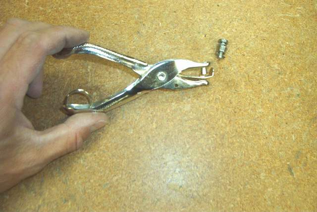
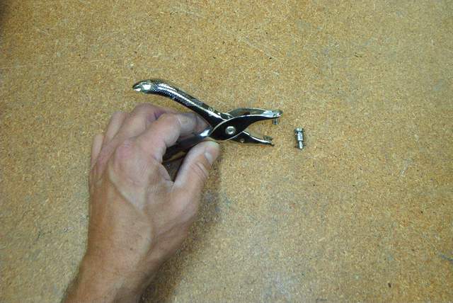
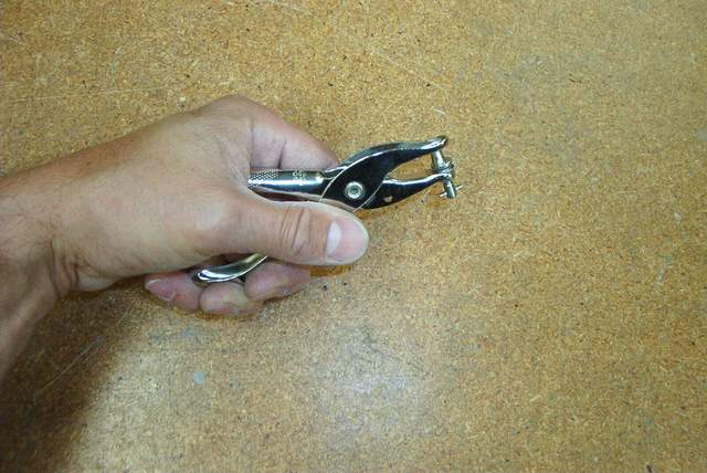 You'll need some expensive camlock pliers to install the studs.... or do
you? A CHEAP paper punch can be converted into a camlock pliers in about
90 seconds..... and it works just fine.
You'll need some expensive camlock pliers to install the studs.... or do
you? A CHEAP paper punch can be converted into a camlock pliers in about
90 seconds..... and it works just fine.
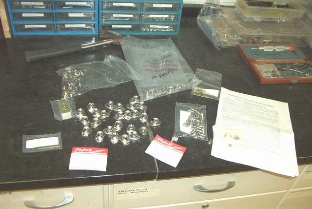
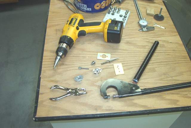 Camlock installation goodies. The cad plated templates that come
with the camlocks aren't worth using, IMHO, since the holes are too big.
The holes that are supposed to be 1/8" rivet holes are so big in the template
that it makes it difficult to drill the holes in the right spot. Then the
receptacle doesn't fit right. Also the large center hole is MUCH larger
than necessary. Suggestion: Make your own
template.
Camlock installation goodies. The cad plated templates that come
with the camlocks aren't worth using, IMHO, since the holes are too big.
The holes that are supposed to be 1/8" rivet holes are so big in the template
that it makes it difficult to drill the holes in the right spot. Then the
receptacle doesn't fit right. Also the large center hole is MUCH larger
than necessary. Suggestion: Make your own
template.
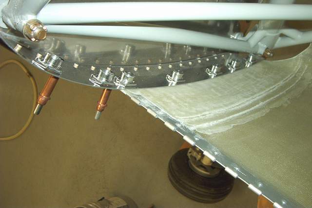
 Camlock installation. Notice the big honking holes required to
install these things.
Camlock installation. Notice the big honking holes required to
install these things.
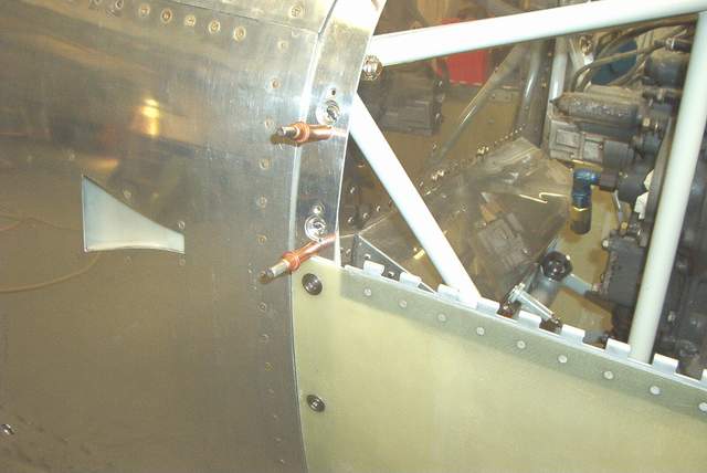
 You might need to add a little flox between the front flanges to get a
good fit. This applies to the flange closest to the spinner too. I
used 3 layers of bid tapes on the flange nearest the spinner to shim it out for
a good fit.
You might need to add a little flox between the front flanges to get a
good fit. This applies to the flange closest to the spinner too. I
used 3 layers of bid tapes on the flange nearest the spinner to shim it out for
a good fit.
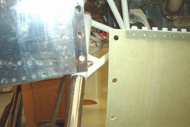
 By now you're proficient at camlock installation and the airbox will only
take a few minutes to install... an hour at the most.
By now you're proficient at camlock installation and the airbox will only
take a few minutes to install... an hour at the most.
 One "gotcha" is the small Skybolt camlocks seem to need an extra washer behind
the retaining washer to keep them from falling out. Hmmm. If I'd
made the hole in the cowling smaller then the camlock wouldn't fit flush on the
outside. But if the camlock fits flush then the hole seems too big.
Catch 22, eh.
One "gotcha" is the small Skybolt camlocks seem to need an extra washer behind
the retaining washer to keep them from falling out. Hmmm. If I'd
made the hole in the cowling smaller then the camlock wouldn't fit flush on the
outside. But if the camlock fits flush then the hole seems too big.
Catch 22, eh.
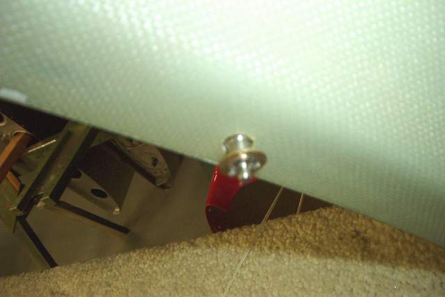
 The gap behind the spinner isn't very even and I'm not sure why. I knew
that this was happening during the entire fitting process but could think of no
way to remedy it short of cutting and reglassing the area behind the prop.
That ain't gonna happen... it's not that bad. Nonetheless, I am puzzled as
to why there is a slight mismatch here. HOWEVER, IT MAKES INSTALLING
THE LOWER COWLING MUCH EASIER, SO THERE IS NO WAY I'D CHANGE IT NOW!!!
The gap behind the spinner isn't very even and I'm not sure why. I knew
that this was happening during the entire fitting process but could think of no
way to remedy it short of cutting and reglassing the area behind the prop.
That ain't gonna happen... it's not that bad. Nonetheless, I am puzzled as
to why there is a slight mismatch here. HOWEVER, IT MAKES INSTALLING
THE LOWER COWLING MUCH EASIER, SO THERE IS NO WAY I'D CHANGE IT NOW!!!
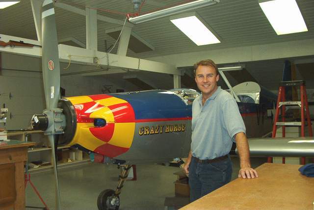 9-10-04... almost ready to go to the airport. Vince *end of comment*
Q: I have the firewall clecoed together on the bench, and my forward facing stainless flanges are trimmed to a beautiful consistent line. That line makes the flange about 3/4 inch. Vans calls out 5/8 for the flange dimension, but that would require trimming another 1/8 all the way around the firewall (major pain). Normally extra meat on a flange isn't a problem, but here it might be important, as it is where the cowl is attached. Can the hinge location be adjusted such that the flange can be left at 3/4 or do I need to work the flange down to 5/8? Aloha, Russ Werner Maui HRII
A: Hi Russ: Heck, leave it as is before you cut your fingers off! Personally, I wouldn't use the hinge -- the stress at the bottom corners at 275 MPH has got to be more than that $3 hinge will take! Even my RV-4 had problems there. I send strips of .040 material with the F1 kits to be used as a cowl attach flange, along with narrower strips of .040 material to be used as shims to move the attach flange back from the skin, and give a smooth profile to the cowl/skin joint. You may have to add some layers of fiberglass to the aft edge of the cowl to get this smooth profile, but in light of the ship's VNE, that reinforcement would be in the 'good thing' category. We use c/s #8 screws along the aft edge of the cowl at roughly 4" sp, but 1/4 turn fasteners will also work. Caveat: the 1/4 turn fasteners are a pain if used behind the spinner and at the outer corners of the cowl -- they don't actually come al the way out when released, you recall, and they get in the way when you are trying to re-install the upper cowl. Use screws here. The hinge method at the upper/lower cowl attach seems to work fine. You can combine the P4/P3 hinge sizes to offset the hinge line slightly above the parting line -- this hides the hinge eyes and gives a smoother look to the part line. Use soft rivets (AN426A3-5) when riveting the hinge to the cowl, and also some JB weld to attach the hinge to the inner sfc of the cowl. Yep -- JB weld! Don't let the JB weld get into the hinge eyes -- scrape it out while it's still soft.
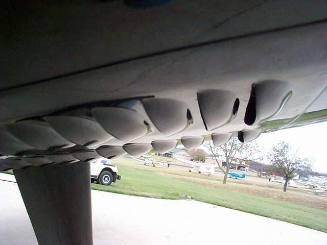
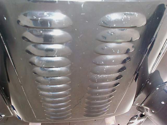
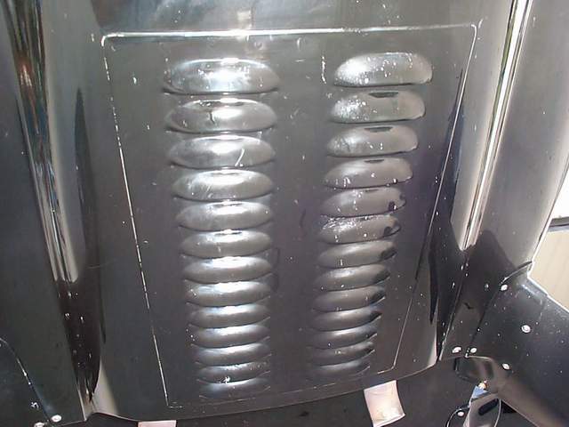
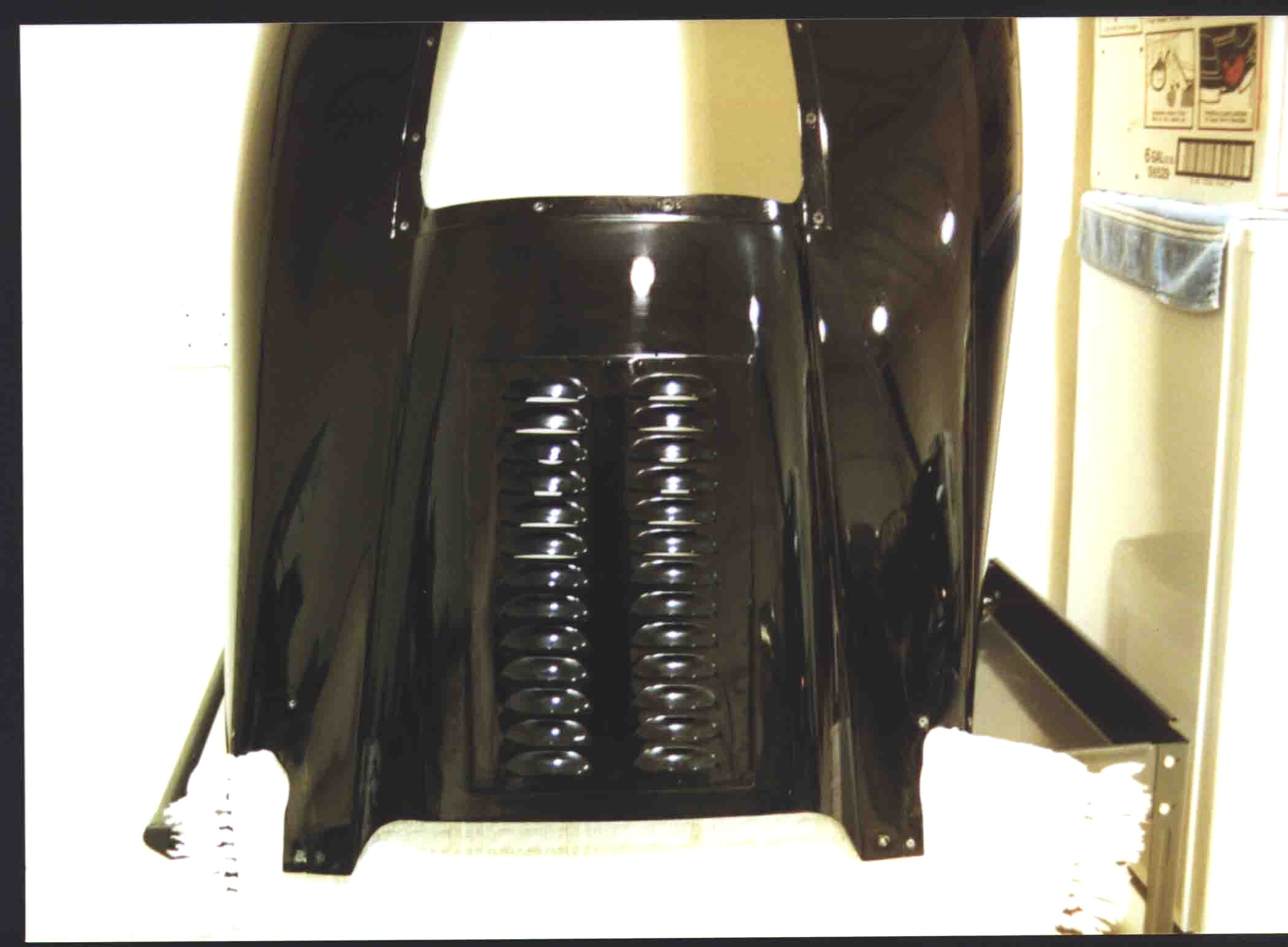
I have been asked to post specifics on the lower cowling louvers installed on Blackjack. This idea came from the RV-8 community when some were having trouble with high oil and cylinder head temperatures. Since our six cylinder produces more heat than the four, I decided to add the louvers right off the bat and before painting the aircraft. So, I can't really tell you how well they work, as I have never flown the aircraft without them.
The thickness of aluminum will be determined by the machine used to punch the louver. Mine were punched on a auto louver machine, and as I recall I used a scrap piece of .032 aluminum.
I started with a piece of aluminum measuring 15''X10''. The width of the louver opening was 3'', and two rows of 13 punches on each row were all I could get on a piece of metal that size.
One word of caution is appropriate. I was concerned about reducing the rigidity of the cowling, so I did not cut a large rectangular hole under the louver. Instead, I cut three round holes, evenly spaced under the louver and about 3'' in diameter. The louvers are riveted to the cowling with a light layer of pro-seal between the cowling and aluminum louver. Hope this helps. Jim Cash *end of comment*
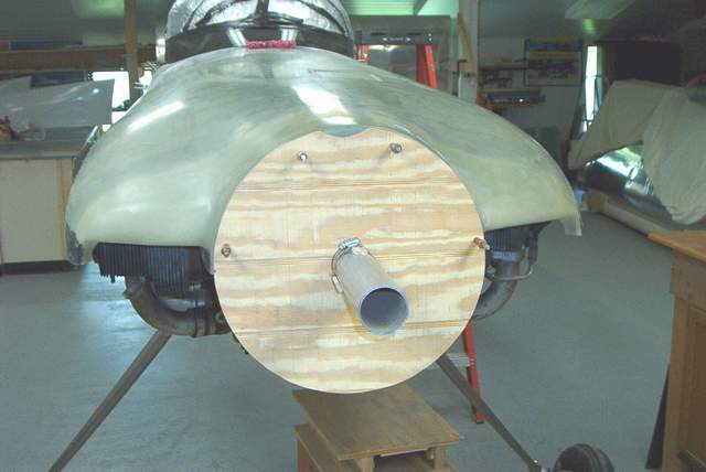
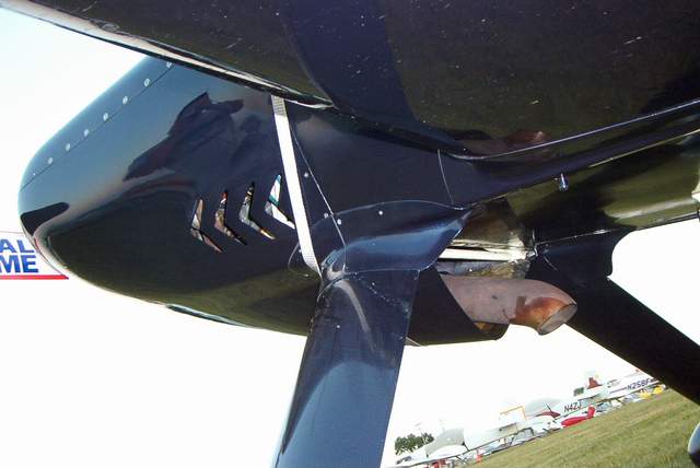 N73MM by Phil Matthews and Jerry Mullins. Check out those
louvers... and that HUGE exhaust pipe.
N73MM by Phil Matthews and Jerry Mullins. Check out those
louvers... and that HUGE exhaust pipe.
Airbox Stuff:
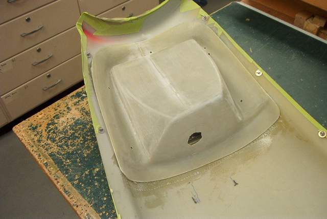
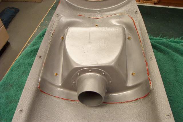
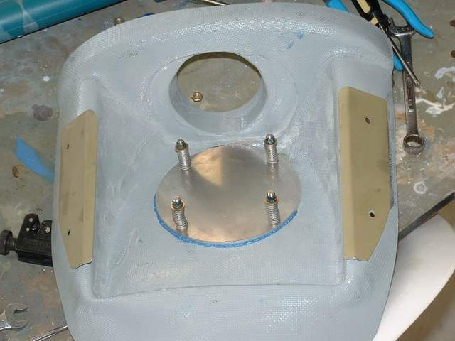
 8-23-04: The filter bracket is trimmed and fiberglassed
into the lower cowl scoop in the usual manner... that is with much swearing and
itching followed by more swearing and more itching. I hate this crap.
8-23-04: The filter bracket is trimmed and fiberglassed
into the lower cowl scoop in the usual manner... that is with much swearing and
itching followed by more swearing and more itching. I hate this crap.
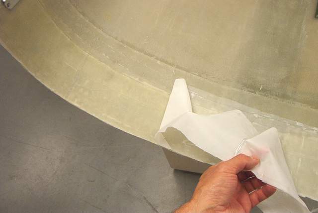
 The filter needed to be trimmed to fit. The hard rubber edge is difficult
to cut. A razor blade does a crappy job, but a belt sander will make a
nice clean edge. Use the belt sander.
The filter needed to be trimmed to fit. The hard rubber edge is difficult
to cut. A razor blade does a crappy job, but a belt sander will make a
nice clean edge. Use the belt sander.
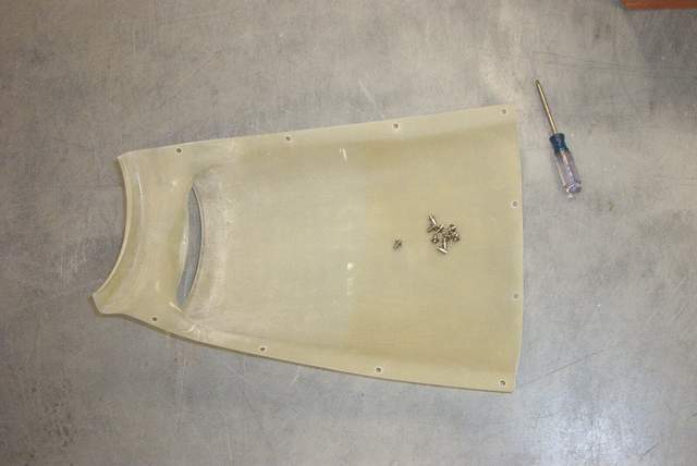
 The cover being fitted.
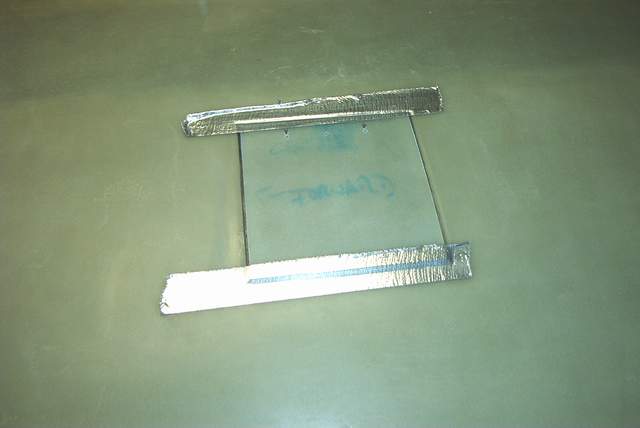
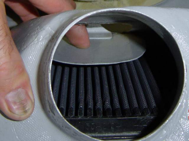
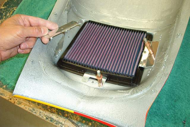 Here's a nifty way to hold the air filter in place. A couple simple
aluminum tabs with "teeth" to grip the filter do the trick nicely.
Here's a nifty way to hold the air filter in place. A couple simple
aluminum tabs with "teeth" to grip the filter do the trick nicely.
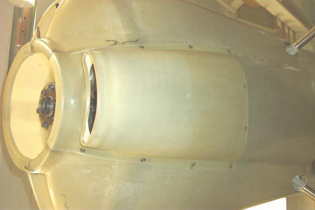
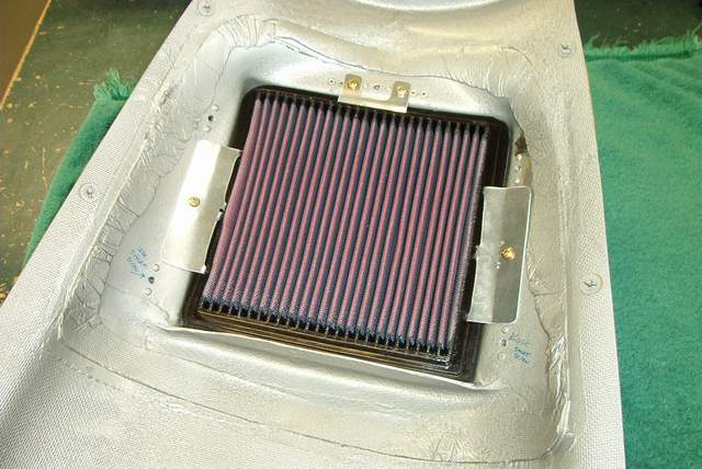 The installed filter.
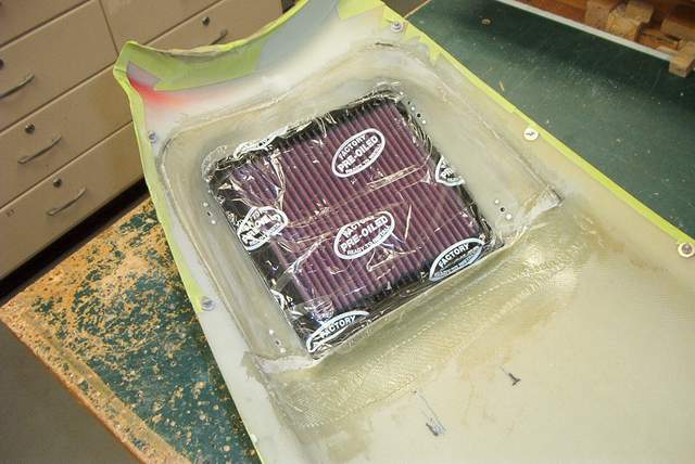
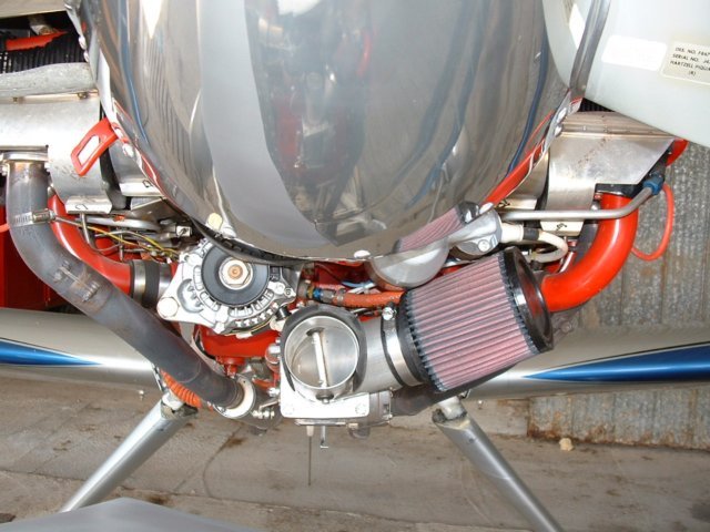
 And finally, the entire airbox. Mark said that they use a piece of SCAT
hose about 2" longer than needed to feed air to the Bendix. I can attest
that the SCEET hose that I had was too stiff to install... so I've got a chunk
of SCAT on order.
And finally, the entire airbox. Mark said that they use a piece of SCAT
hose about 2" longer than needed to feed air to the Bendix. I can attest
that the SCEET hose that I had was too stiff to install... so I've got a chunk
of SCAT on order.
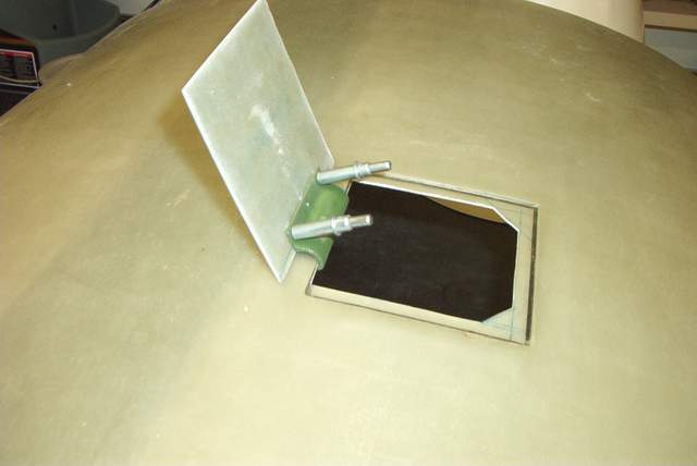
Hmmm, I don't have a photo of the alternate air door that I mounted on the flat top of the airbox... I'll have to get one later.
More Airbox Stuff:
The picture that you see are of the HRII. This plane has a forward mounted Bendix injector. On the front of the injector I have one of John Harmon's Y valves. One half of the Y goes to a round air filter that is in the cowling just under the starter. The other part of the Y goes directly to the smile on the cowling. When you go to ram air the air bypasses the filter and goes directly to the engine. I only use ram air above 5000 feet, it is the only time my power is limited by manifold pressure. I estimate that I pick up half to three quarters of an inch of manifold pressure with the direct unfiltered air. 90% of my flying is with the filtered air and as there are no other rockets around here I feel that I have enough power!! The extra boost of unfiltered air really does not get you that much speed. This system offers the advantage of alternate air, however a direct bird strike might make the valve inoperable.
The system that Mark has designed gets the same pressure rise, or more, than I get with the unfiltered air on the HRII. It has pretty good pressure recovery, much better than I would have though. I believe that the little plenum aft of the filter must be optimum in size. I stayed with the supplied cone adapter on the back of it for two reasons; one, it was cut short of the Bendix by about an inch which pretty much guaranteed the SCAT or SCEET that you use could not collapse. Secondly; it makes the filtered air box easy to remove, there would be no way to tighten up a clamp on the front of the unit. Yes I know that it is not a perfect situation having a minor constriction here but I balance that with the safety and ease of use aspects. I think in the long run the round hole inlets have the potential to offer better induction air but the modifications to the current system are more than I care to do at this time.
I would like to have some sort of automatic alternate air. I think it would be impossible for a bird strike to completely block of this system. If you hit a bird that is large enough to block the F1 airbox then you have bigger problems than induction air!! Living where I do, with snow in the air this time of year, sometimes visibility is not really hampered but I have no way of knowing how it is affecting the filter.
The little magnet on a door idea sounds good. It would be an easy mod to make as the airbox supplied has a nice flat spot on top. The problem that I have with the automatic systems is not knowing if they will open when they are not supposed to, or worse yet will they open if needed. There is no ram pressure while you are on the ground to hold that door shut, in fact the suction of the engine might pull that door open rather than pulling through the filter. If you make the magnet strong enough to resist opening at start up, will it open when needed? Perhaps some sort of warning light? I look forward to seeing what Bob Gross is working on.
Tom Martin
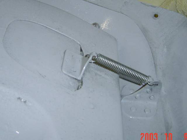
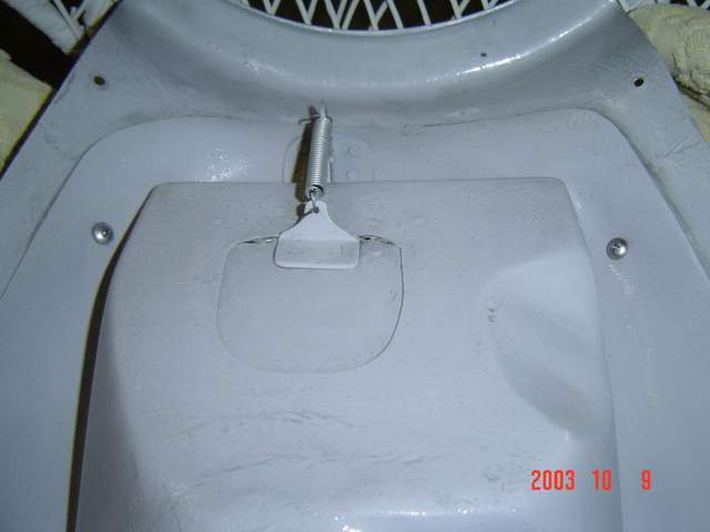
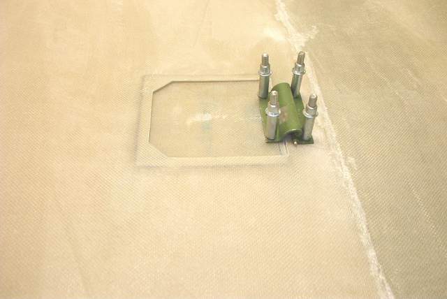
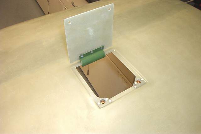
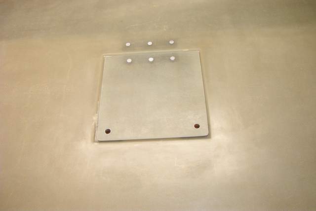
Greg Nelson posted these pictures of his alternate air door mounted on a stock F-1 airbox.
 Another alternate air set up. Very simple and elegant. Just a spring
loaded disk.
Another alternate air set up. Very simple and elegant. Just a spring
loaded disk.
Return to the homepage:
http://www.vincesrocket.com/
Last updated:
09/01/06
CAUTION: This web site is not a publication of, nor approved by, Harmon LLC, Team Rocket, Van's Aircraft or any other person or entity listed herein, except me. Be advised that I am a blithering idiot with neither brains nor money and my advice is not to be trusted. So there. You have been warned! Vince