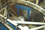
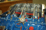
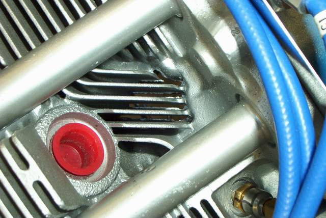
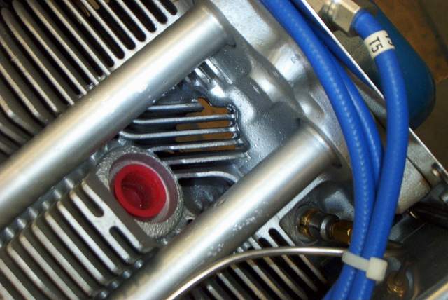
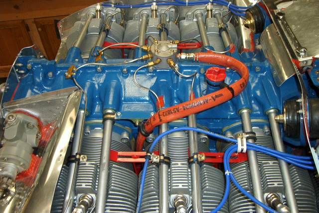
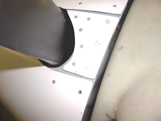
10-17-05: An easily overlooked item that is almost guaranteed to
make your Lycoming parallel valve #2 and #5 cylinders run hotter than they
should is baffles that are too tight. WHAT? Yeah, too tight in
certain areas. Check the photo below. Once you look at a real
cylinder you'll say "Doh! Why didn't I think of that?!"
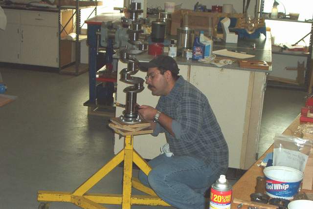
8-23-04: Lately there has been much discussion online about
excess flashing in the cooling fins between the sparkplugs. It is accused
of being a possible cause of high CHT's.
I don't have any data as to whether the removal of the excess
material helps cooling or not.
Others have reported that the removal of the excess material
took "hours and several drill bits." Yuck. A drill bit isn't a good
tool for this job. Here's an easy way to rid your cylinders of the excess
material. And it will take less than an hour, including removal of the
spark plugs and sweeping the floor afterwards. It only takes about two
minutes to do the actual filing on each cylinder.
Even though the job took less than an hour and the appearance of
the cooling fins were certainly improved, there's always a downside... The
air file can "grab" on the flashing and stick firmly. This causes the airfile to rattle your teeth. No harm is done UNLESS the airfile is
touching one of the fragile pushrod tubes. It will dent the shit out of
those tubes. Ask me how I know!! I made a nice dent on the
very first try. You MUST protect the pushrod tubes by keeping your
hands, BOTH of them, on the airfile. Position your hands so that if the
airfile sticks you will not hit the pushrod tubes or the injection lines.
If you do this you won't have any problems. Have fun! Vince
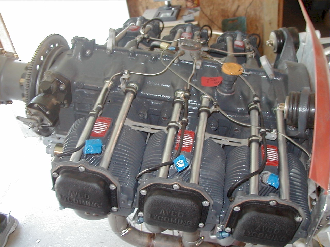
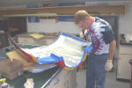
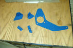
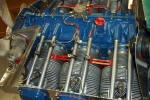
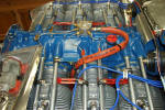
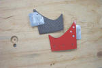
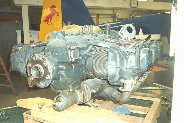
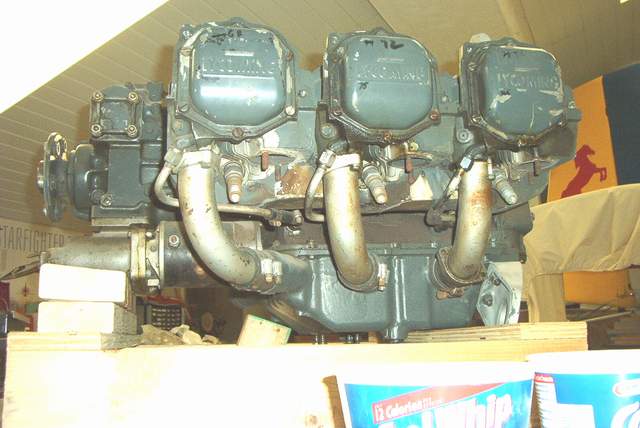
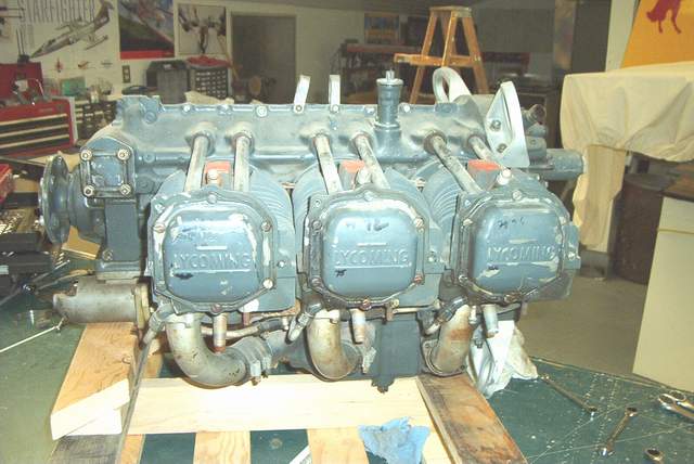
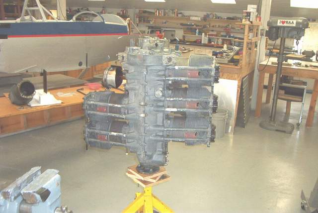
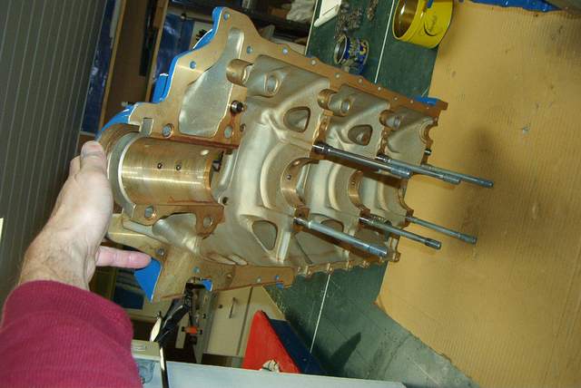
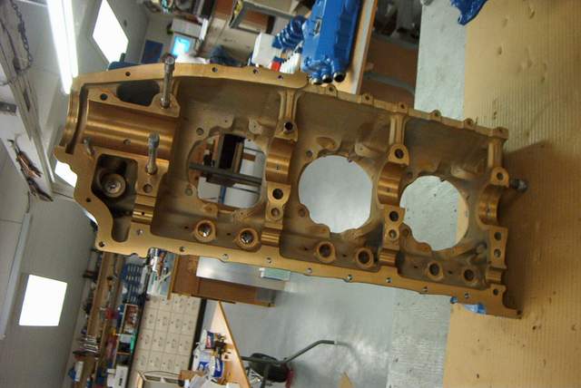
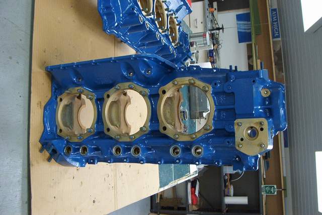
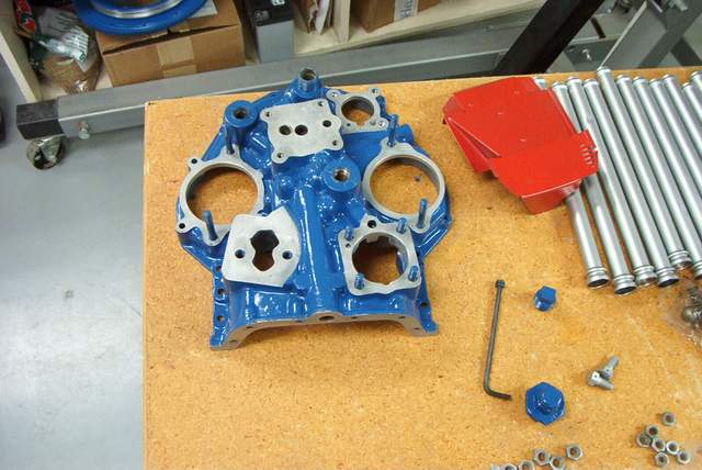
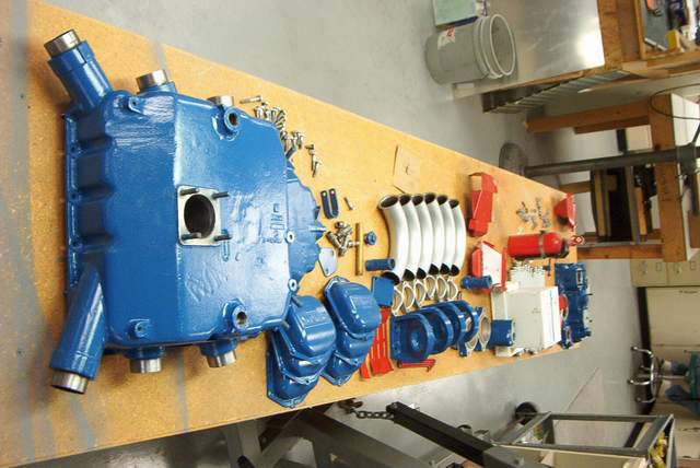
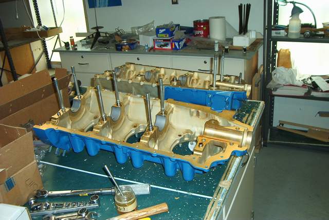
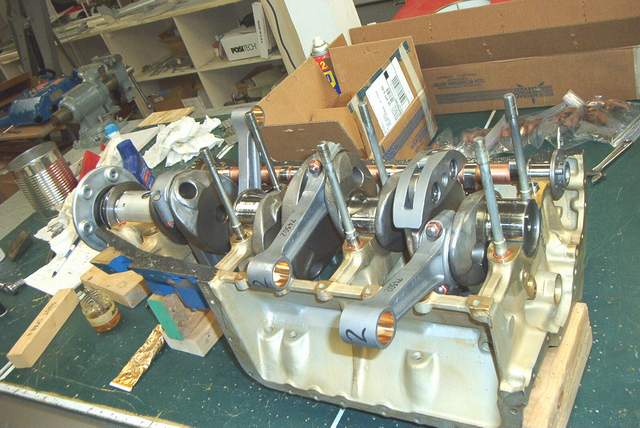
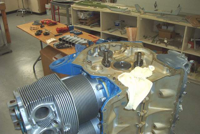
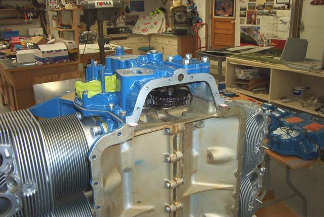
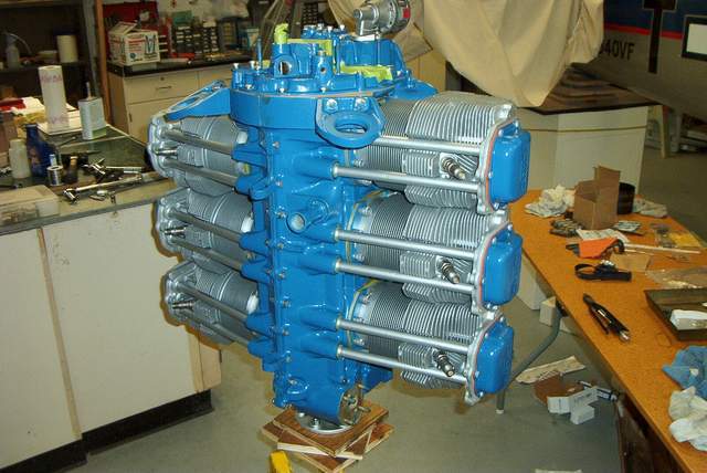
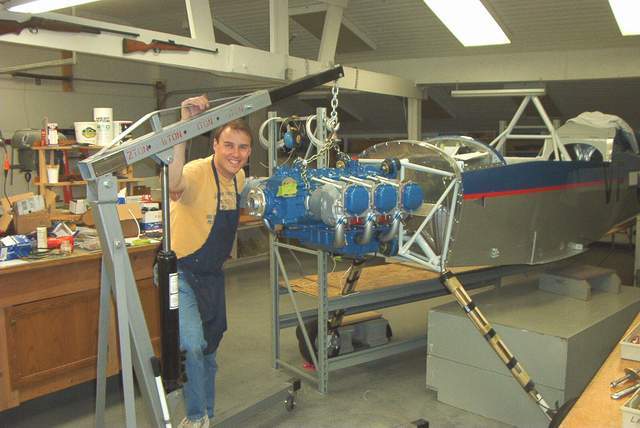
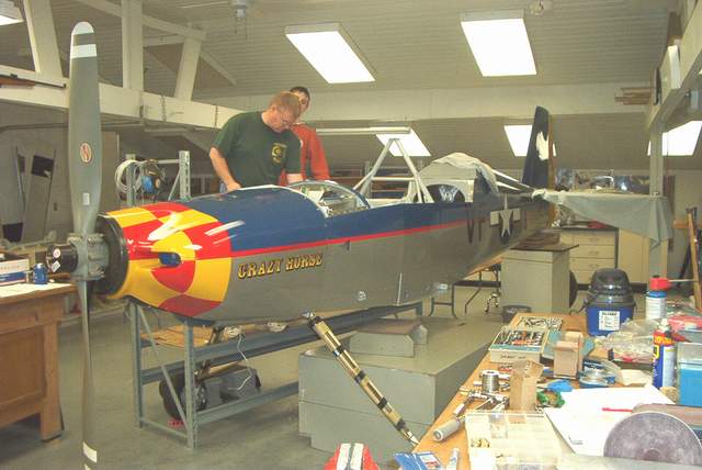
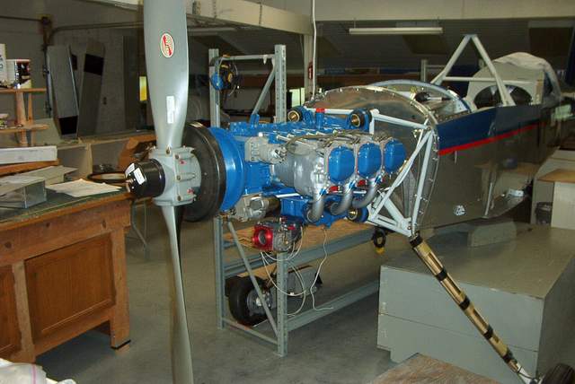
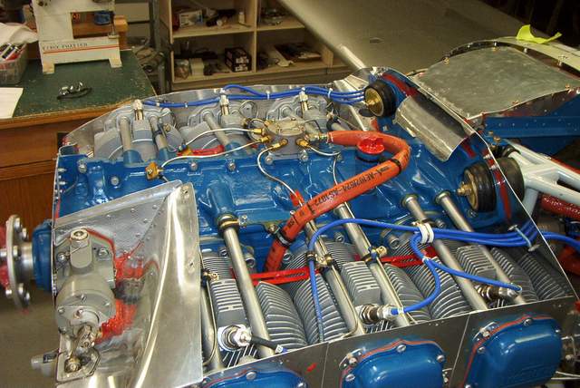
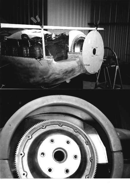
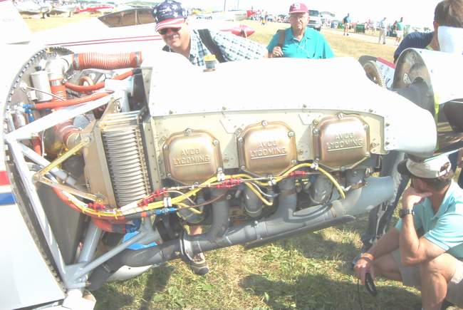
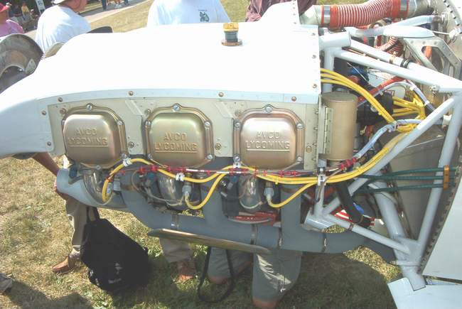
Here are the same parts after they came back from Divco and
Aircraft Specialties Services. You have to apply the paint yourself.
I went down to Autozone and bought a few cans of their engine paint in red,
silver, and blue. Use grease to mask off the areas that don't get painted,
like the cylinder base areas. After the paint dries just wipe off the
greased areas.
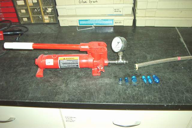
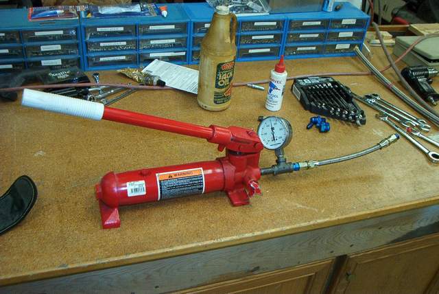
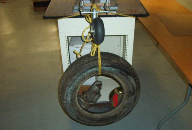
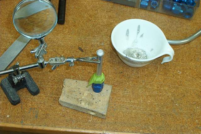
Well, there are other ways to bend tubing than with one of those
shitty benders. Get a pound of CERROBEND from your wife who works in
radiation therapy at the local hospital. Other low melting alloys or even
packed sand will work. Sand sucks to work with, but CERROBEND, which melts
at 225 degrees F is perfect.... except for the toxic lead fumes.
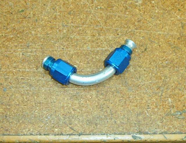
It's pretty obvious from the pictures, but first you flare the
tubing on both ends after you install the fittings! Then pour in the
molten CERROBEND. Cool and bend carefully. Reasonable bends are easy
but it is possible to crack the aluminum if you get too aggressive. Simply
remelt the CERROBEND while being careful not to overheat the aluminum. The
CERROBEND will come right out. Clean the tubing like you would any other
before you install it.
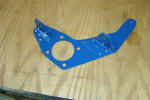
Engine baffles:
There are many ways to make your engine baffles. Several
are shown below. Here's what I did:
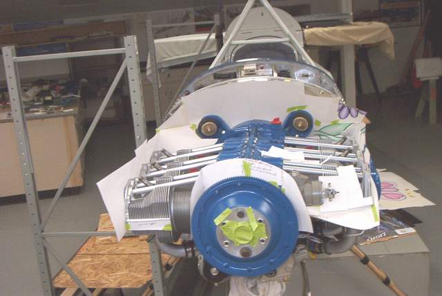
 5-17-04: I had plenty of leftover .032 aluminum, a set of
Jack Gray's baffle templates printed out, and an empty checkbook so I decided to
make my own baffles. A tedious job for sure, but not any worse than any of
the 101 other tedious jobs done so far.
5-17-04: I had plenty of leftover .032 aluminum, a set of
Jack Gray's baffle templates printed out, and an empty checkbook so I decided to
make my own baffles. A tedious job for sure, but not any worse than any of
the 101 other tedious jobs done so far.
Since I wanted a fully enclosed plenum, I knew that some
modifications were needed to Jack's drawings. I started out by cutting out
all of the paper templates. I soon realized that either I am an idiot or
that some of the drawings weren't quite right for my engine. I'm not sure
which, but either way I needed to make a few of the rear templates out of
cardboard.
As you can see in the photos, it's important to obtain the stiff
cardboard from your daycare's leftover bin. That way you'll have plenty of
flowers already drawn on the cardboard. :-)
 Like I said, I had no luck figuring out how the rear wall of the baffles fit
together, so I made my own using Jack's drawings as a guide.
Like I said, I had no luck figuring out how the rear wall of the baffles fit
together, so I made my own using Jack's drawings as a guide.
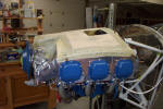
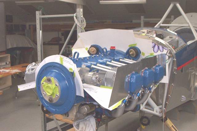
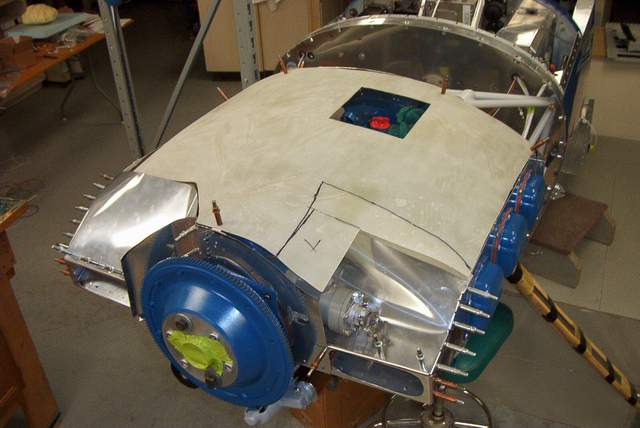
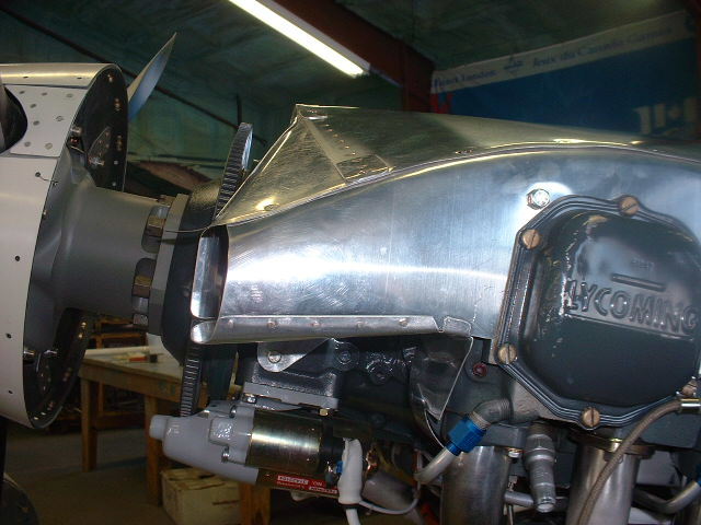
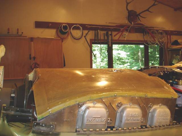
 6-2-04: The plenum sides are taking shape nicely. So far everything
looks good... even if it's not quite to the final shape yet.
6-2-04: The plenum sides are taking shape nicely. So far everything
looks good... even if it's not quite to the final shape yet.
 The inlets were shaped so that they would match the holes in the cowl.
They will get a serious trimming later after everything else is finished.
Right now they are more for holding the other stuff in place. They aren't
very aerodynamic in this boxy form.
The inlets were shaped so that they would match the holes in the cowl.
They will get a serious trimming later after everything else is finished.
Right now they are more for holding the other stuff in place. They aren't
very aerodynamic in this boxy form.
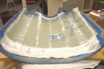
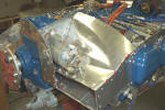
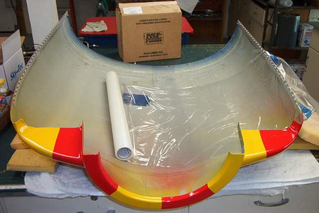
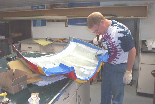
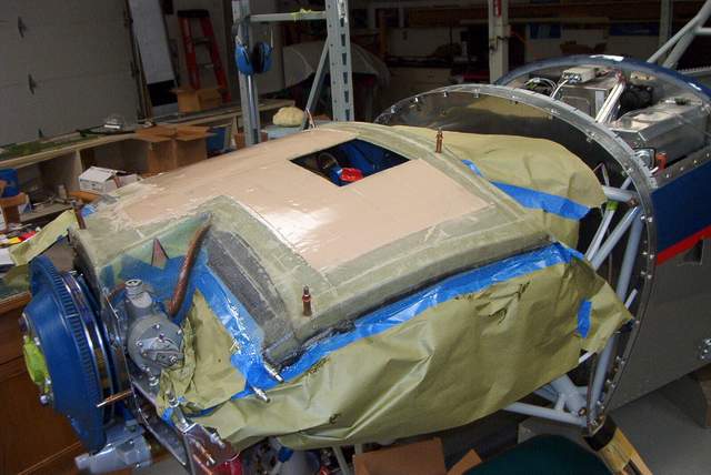
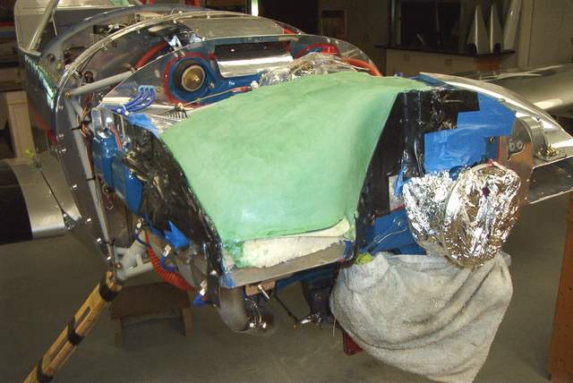
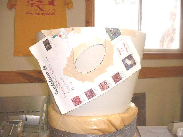
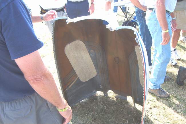
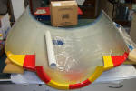 6-3-04: Someone had the brilliant idea to use the
top cowl as a female mold to make a fiberglass top for the plenum. I had
to try it.
6-3-04: Someone had the brilliant idea to use the
top cowl as a female mold to make a fiberglass top for the plenum. I had
to try it.
I used clear, sticky backed carpet protector (like a contractor
puts down in a new house to keep the carpet clean) to protect the cowl from the
resin. It works OK, not good, but OK. It peels off easily, but is
tough to get to lay down without creases. Next time I'd just use 2" wide
painter's masking tape, the kind that comes off easily. Whatever you use,
be sure to brush a layer of Partall mold release on top so the resin won't
stick.
 A layer of resin gets brushed in and the first of 6 layers of BID cloth goes in.
 John stipples the bubbles out.
 A layer of peel ply neatens up the inside.
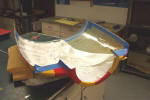
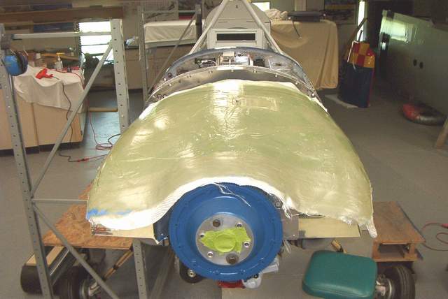
 Hey, it fits. Well, good enough to be a decent starting point
anyway.
Hey, it fits. Well, good enough to be a decent starting point
anyway.
 Need to remove the tape that is still stuck in place.
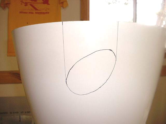
 Voila! A few minutes of trimming and we'll be in business!
 The rough trim.
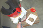
 Making a "mold" using tape, cardboard, dead animals, heavy paper, whatever is
handy! When Long Eze builders look at my fiberglass work, their jaws
always drop. I guess they're impressed. I'm impressed that anyone
would build anything out of this sticky, carcinogenic crap.
Making a "mold" using tape, cardboard, dead animals, heavy paper, whatever is
handy! When Long Eze builders look at my fiberglass work, their jaws
always drop. I guess they're impressed. I'm impressed that anyone
would build anything out of this sticky, carcinogenic crap.
 Adding a flange around the edges and filling the ugly work I'd done on the top
piece.
Adding a flange around the edges and filling the ugly work I'd done on the top
piece.

 Hmmmm, not too bad after all.
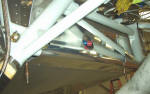
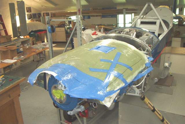
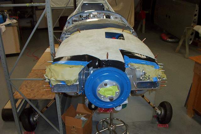
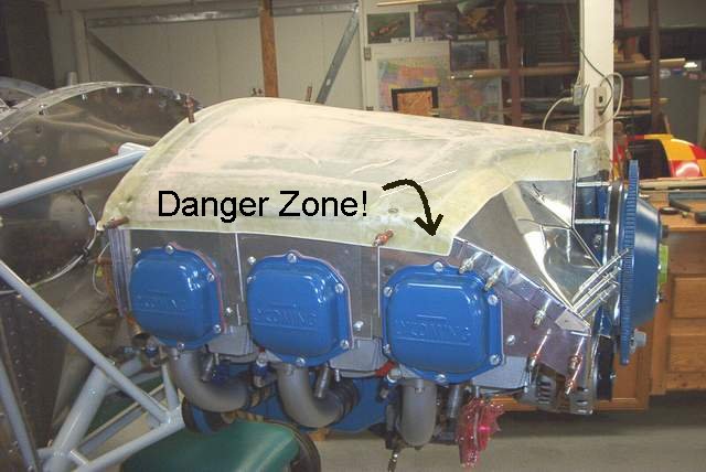
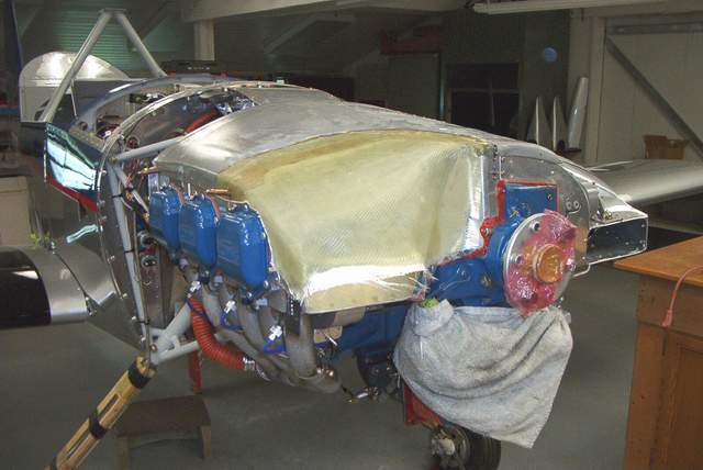
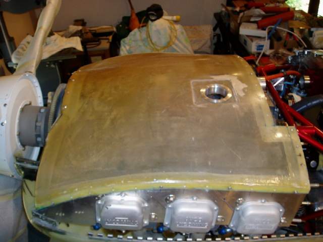
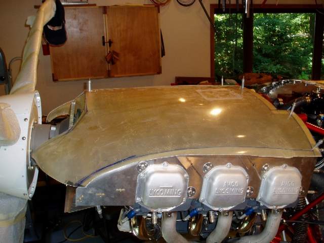
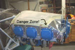 6-15-04: Everything was going well until Murphy
showed up and reminded me that the cowl clearance is tight...REALLY TIGHT....
above the #1 cylinder. The beautifully molded fiberglass masterpiece that
I slaved over hit the cowl top. DOH! Not bad, but bad enough that it
needed to be lowered (pictures to come later). In this picture the arrow
points to the area that is about an inch too tall!!!! DOH!
6-15-04: Everything was going well until Murphy
showed up and reminded me that the cowl clearance is tight...REALLY TIGHT....
above the #1 cylinder. The beautifully molded fiberglass masterpiece that
I slaved over hit the cowl top. DOH! Not bad, but bad enough that it
needed to be lowered (pictures to come later). In this picture the arrow
points to the area that is about an inch too tall!!!! DOH!
I'll post more pictures of that later, but trust me here, if
you're building a plenum like this it MUST be so close to the #1 spark plug that
you can't get the wire on. Yup, that close. I had to make a 90
degree in the spark plug wire about 3/8" above the spark plug (pictures to come
later). Japundza tells me that you can get shorter spark plugs.
REM37BY from Van's. I have no clue if they'd be short enough or not.
Too late for me though.
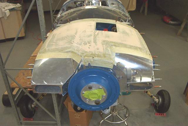
 Final fit and fill (not anymore!!!! I wasn't happy
with the way the right inlet was looking so I remade it. See below.)
Final fit and fill (not anymore!!!! I wasn't happy
with the way the right inlet was looking so I remade it. See below.)
 The piece is painted using Rustoleum Hammered
Finish silver paint. It works very well and fills the weave well also.
In fact, it worked so well that I plan to paint the inside of the cowling with
it.
The piece is painted using Rustoleum Hammered
Finish silver paint. It works very well and fills the weave well also.
In fact, it worked so well that I plan to paint the inside of the cowling with
it.
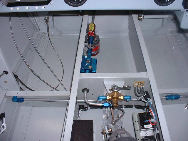
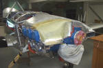
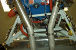
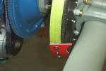
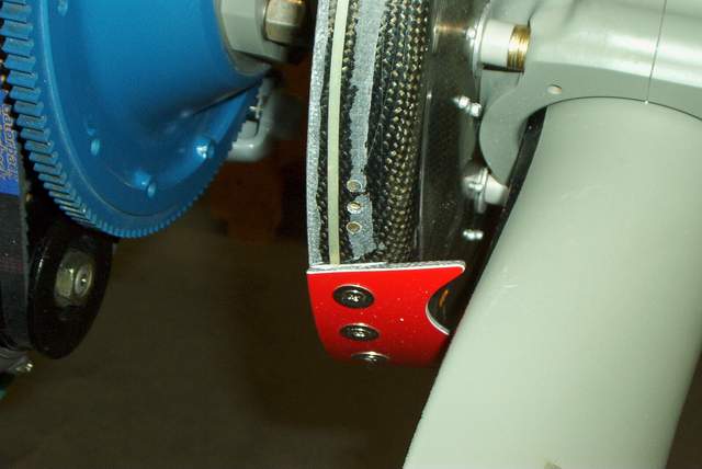
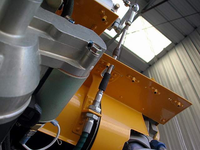
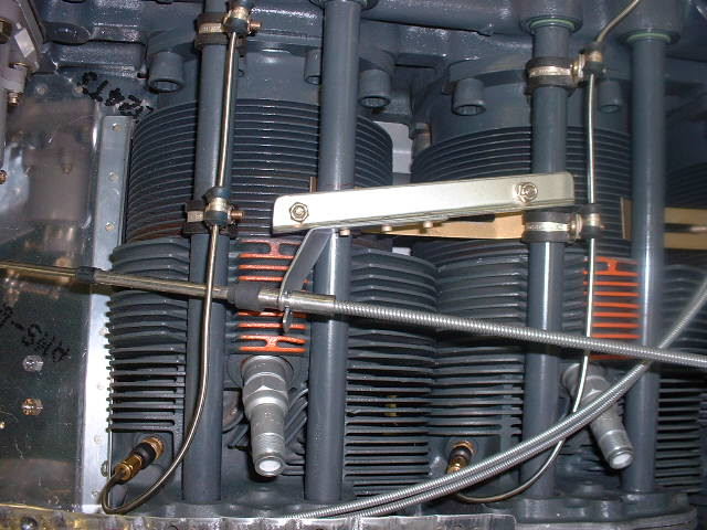
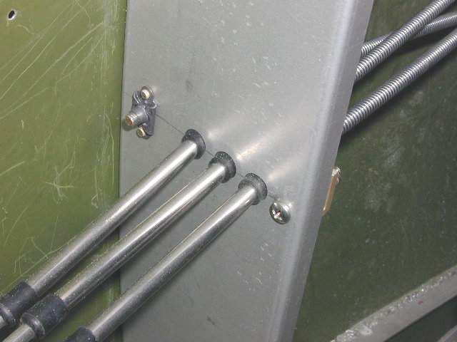
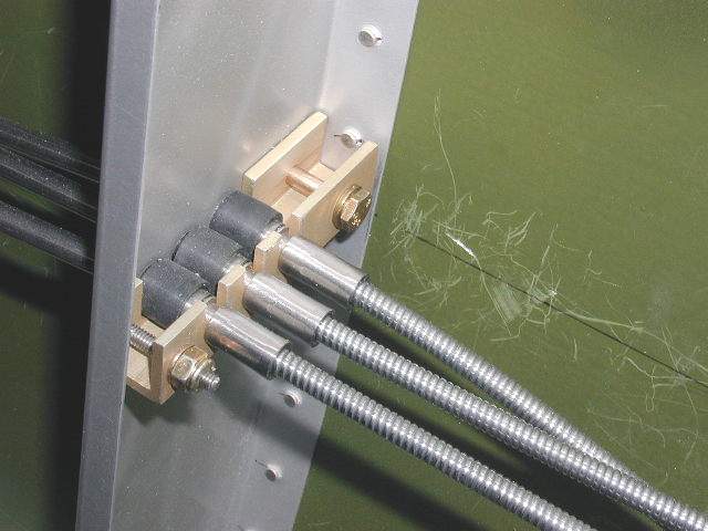
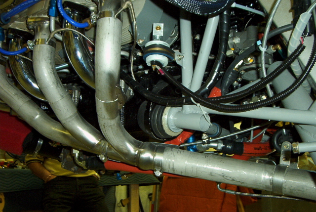
 7-21-04: The governor cable passes through my plenum... an annoying design flaw
on my part, but one that I'll live with because I want to get this thing in the
air this year. The little gap seals are made from baffle material
and are slit into tiny slivers sorta like a comb. This allows the rod to
move freely, yet helps block some of the air leakage. It's not the most
cosmetically beautiful work I've ever done but it seems to work well.
7-21-04: The governor cable passes through my plenum... an annoying design flaw
on my part, but one that I'll live with because I want to get this thing in the
air this year. The little gap seals are made from baffle material
and are slit into tiny slivers sorta like a comb. This allows the rod to
move freely, yet helps block some of the air leakage. It's not the most
cosmetically beautiful work I've ever done but it seems to work well.
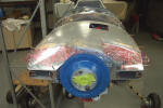
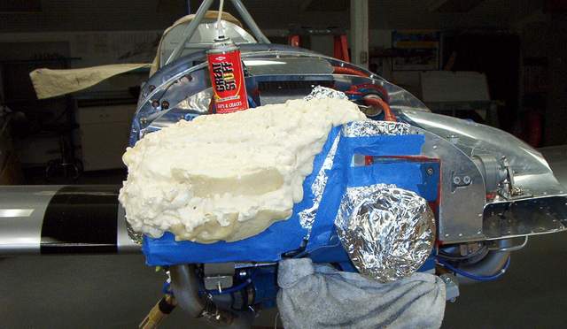
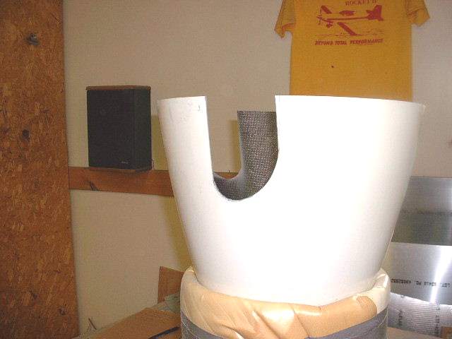
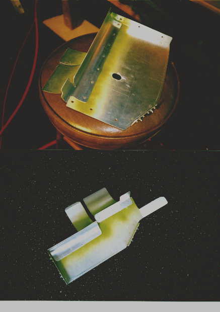
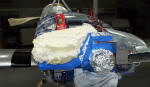 9-2-04: I wasn't happy with the opening of the right
inlet. The aluminum kluge that I had cobbled together just didn't look
like there was enough room to flow any air. What to do??? Get the
airsaw and do some serious surgery, foam the vacant hole, then shape a new,
improved plenum inlet.
9-2-04: I wasn't happy with the opening of the right
inlet. The aluminum kluge that I had cobbled together just didn't look
like there was enough room to flow any air. What to do??? Get the
airsaw and do some serious surgery, foam the vacant hole, then shape a new,
improved plenum inlet.
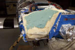 After trimming to foam, you fill it with Bondo. (Please note that this is
the only acceptable use for Bondo anywhere on the airframe, IMHO.)
After trimming to foam, you fill it with Bondo. (Please note that this is
the only acceptable use for Bondo anywhere on the airframe, IMHO.)
 After the Bondo is nice and smooth, you brush on several coats of PVA mold
release. Wicks sells it.
After the Bondo is nice and smooth, you brush on several coats of PVA mold
release. Wicks sells it.
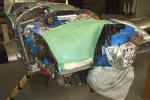
 Well, well, now that's a much more nicely shaped inlet than before!
 The initial trim looks like it might even fit.
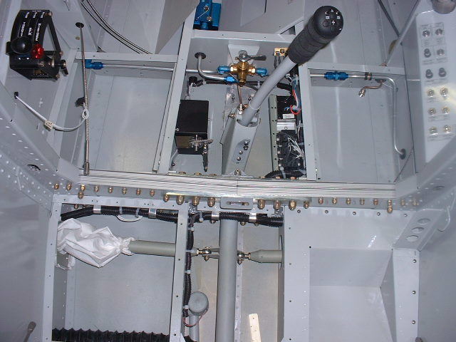
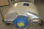
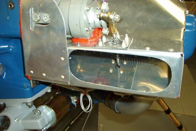
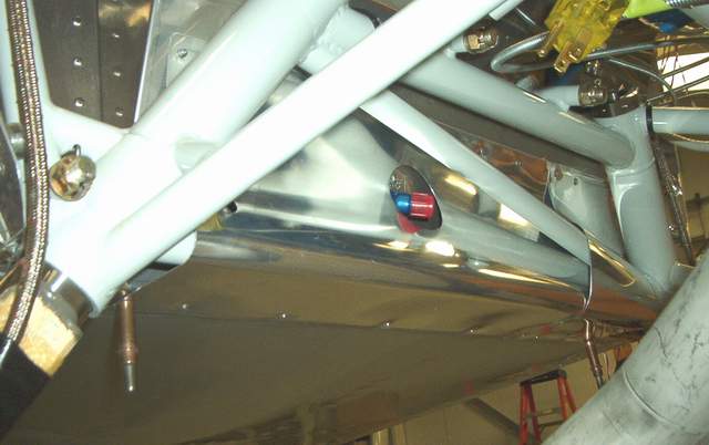
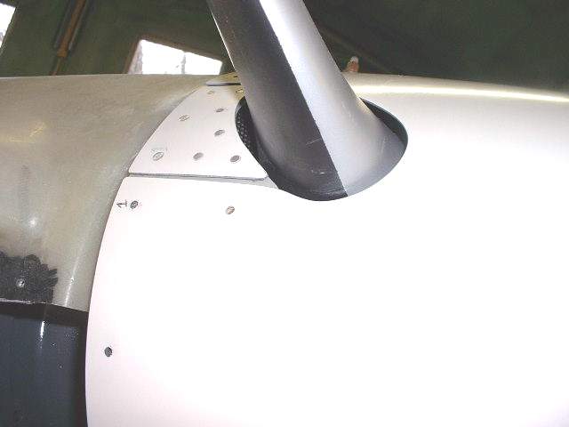
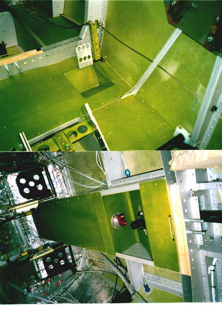
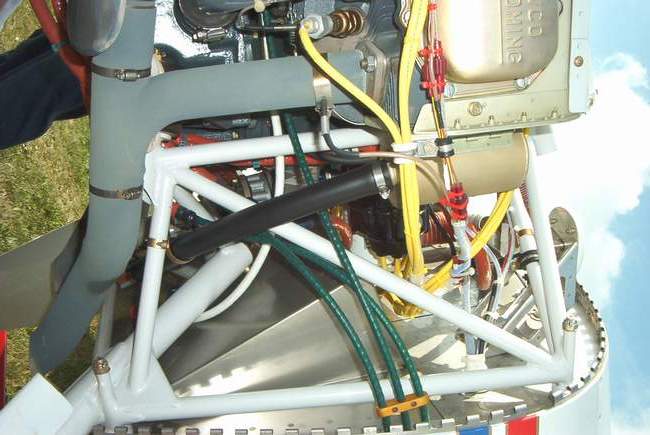
 The left inlet will stay as is.... for now anyway. The left inlet seems to
have a fairly smooth path for the air to enter the plenum. As you can see,
the prop governor is above the plenum entrance. If it doesn't work, I'll
simply redo this side to match the other side. That will put the governor
in the air stream.... is that good or bad??? Time will tell.
The left inlet will stay as is.... for now anyway. The left inlet seems to
have a fairly smooth path for the air to enter the plenum. As you can see,
the prop governor is above the plenum entrance. If it doesn't work, I'll
simply redo this side to match the other side. That will put the governor
in the air stream.... is that good or bad??? Time will tell.
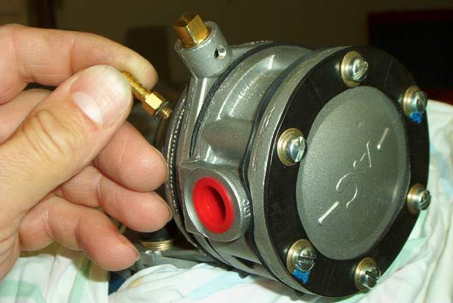
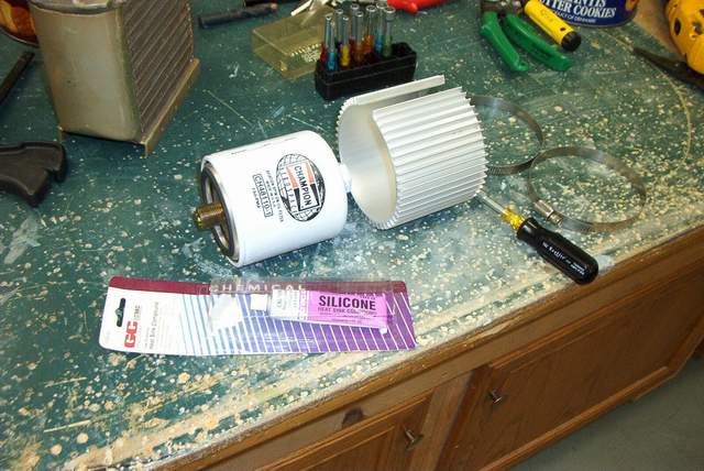
OIL COOLER:

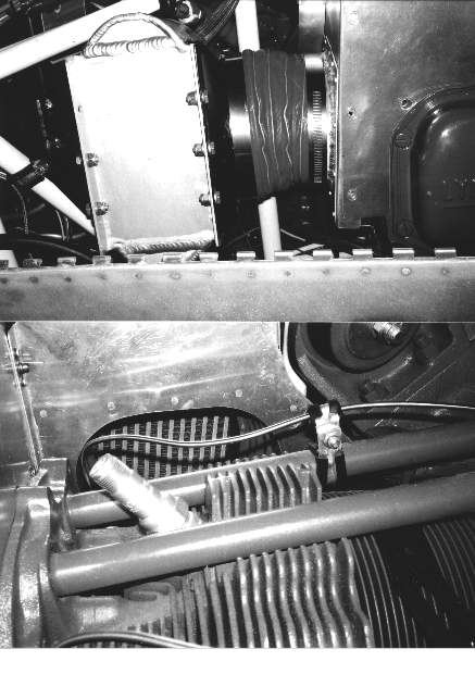
 7-21-04: Given the HOT reputation of the Rockets, I wanted to maximize my oil
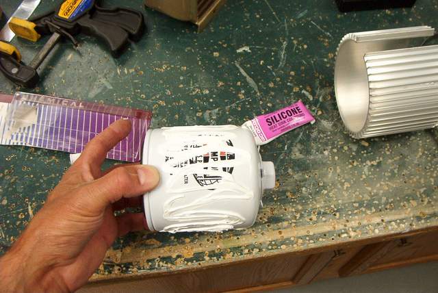
cooling right form the start. I decided to give the Cool Collar a try.
For $30, what the heck. That's almost free in airplane dollars.
7-21-04: Given the HOT reputation of the Rockets, I wanted to maximize my oil
cooling right form the start. I decided to give the Cool Collar a try.
For $30, what the heck. That's almost free in airplane dollars.
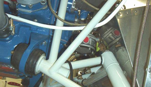
I don't know if everyone else does it this way or not, but in my
opinion you'd be wasting your time to install one of these without first
applying a good dose of silicone heat sink compound to transfer the heat.
The silicone is rated to 400 degrees F, so the oil temps certainly won't hurt
it. It is messy, but probably well worth it.

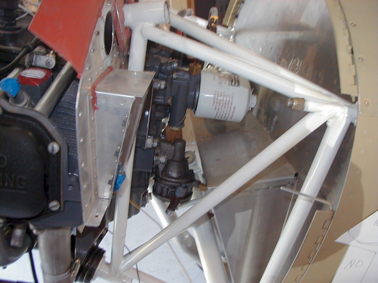
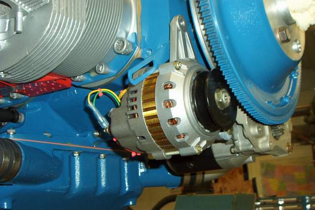
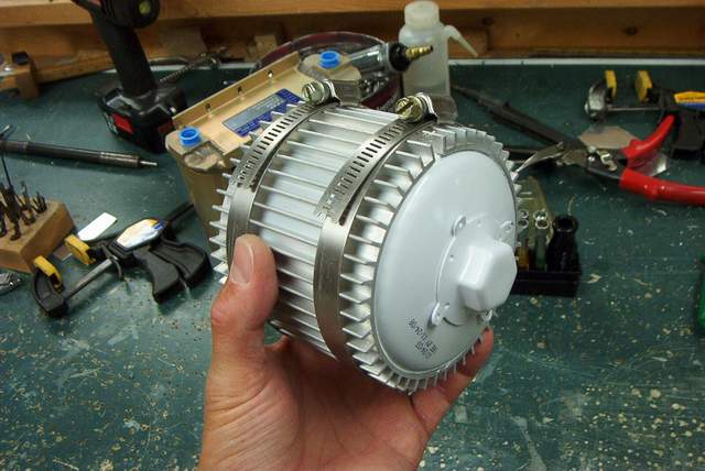
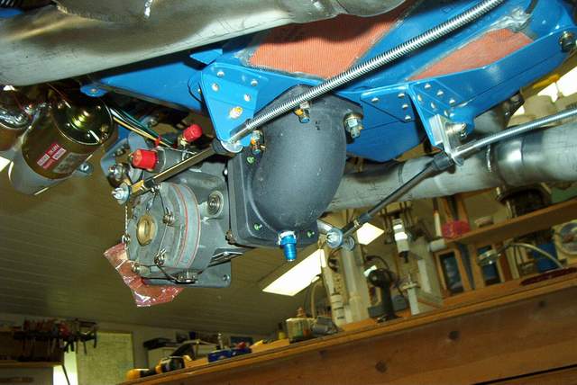
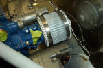 Here's the Cool Collar installed after I cleaned out all of the oozing silicone
heat sink compound. Even with the completed oil cooler in the way (see
below) and all of the hoses/plug wires installed, I can still remove the oil
filter WITH the Cool Collar installed quite easily. I'll report later as
to whether it actually helps to cool the oil.
Here's the Cool Collar installed after I cleaned out all of the oozing silicone
heat sink compound. Even with the completed oil cooler in the way (see
below) and all of the hoses/plug wires installed, I can still remove the oil
filter WITH the Cool Collar installed quite easily. I'll report later as
to whether it actually helps to cool the oil.
I did get a face to face PIREP from a Pitts driver who reports
that he used this exact technique on his Pitts and got a 10 degree drop in oil
temps. He used the silicone heat sink compound to transfer the heat also.
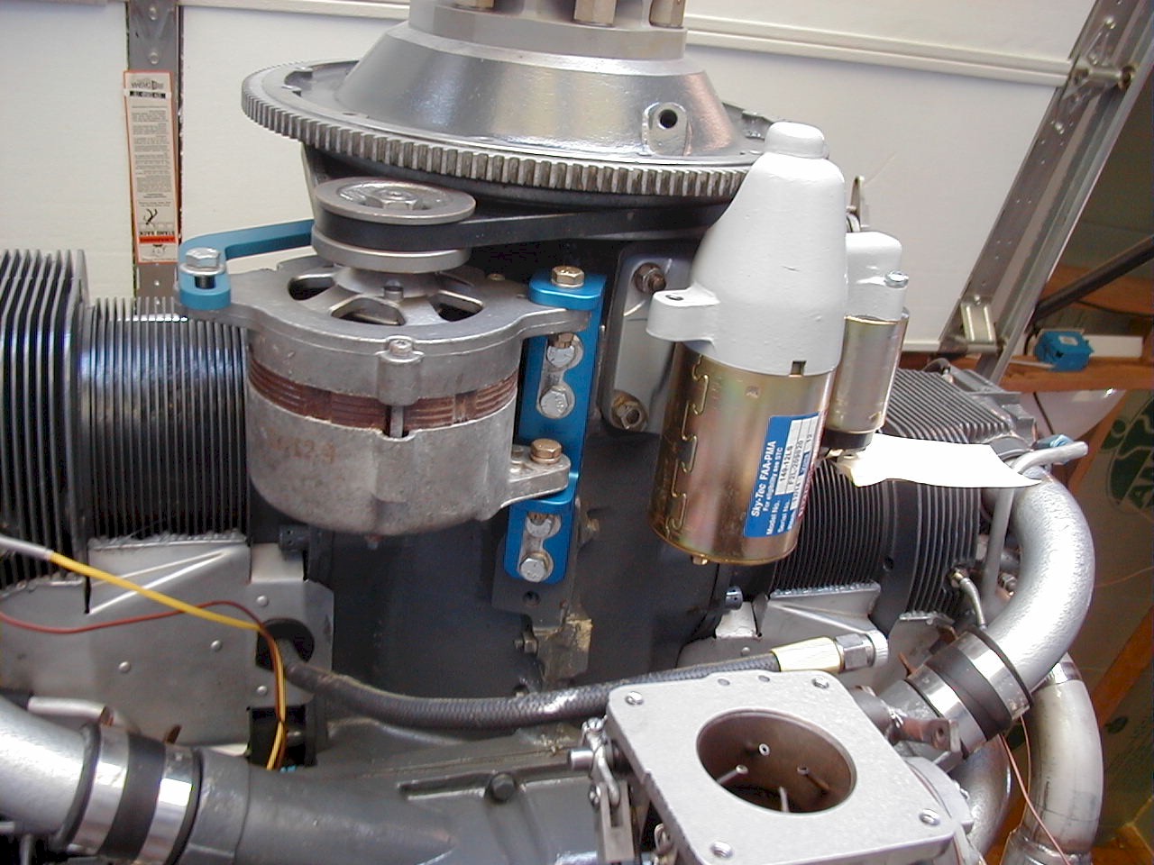
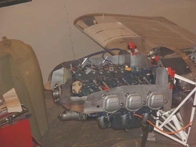
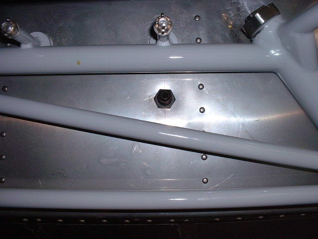
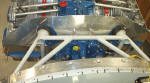
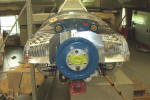
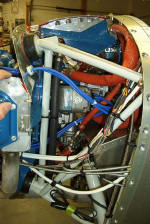
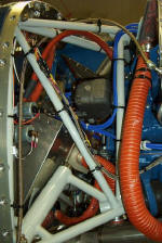
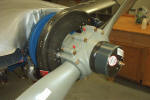
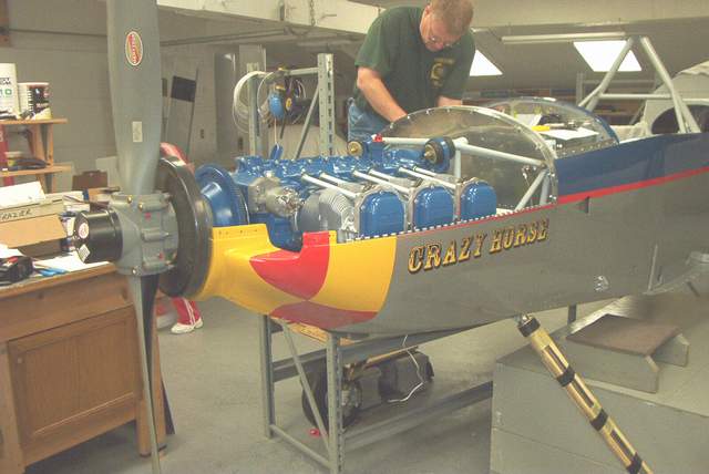
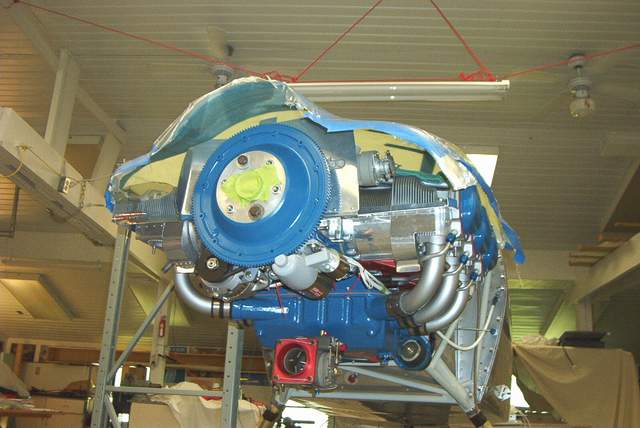
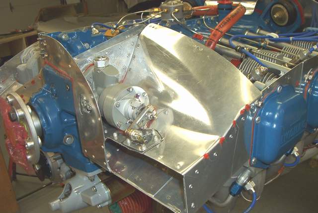
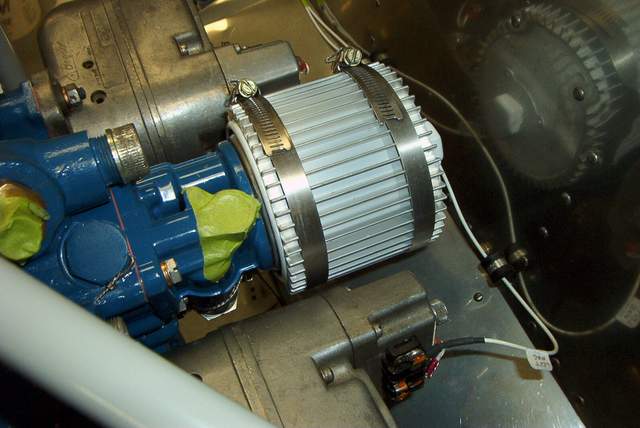
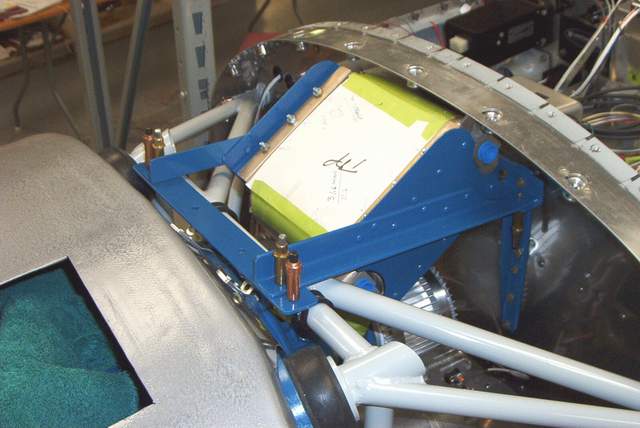
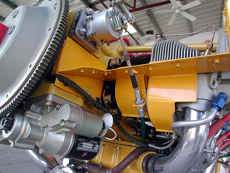
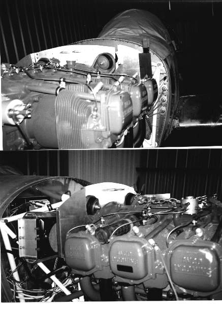
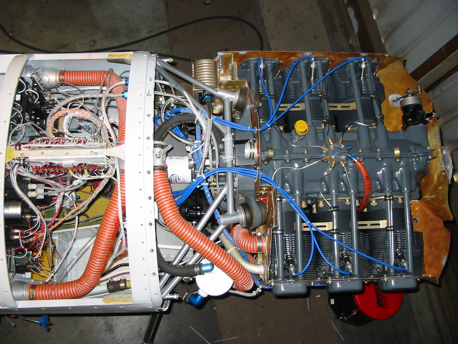
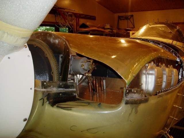
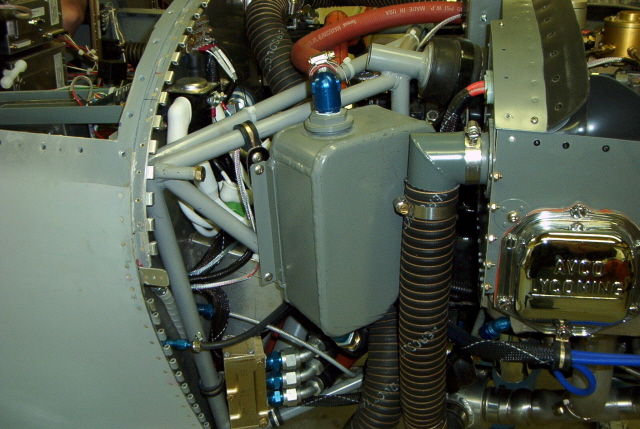
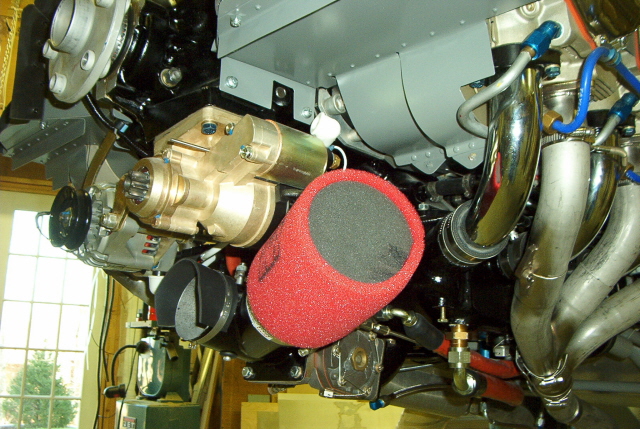
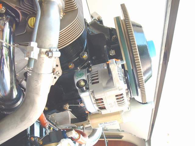
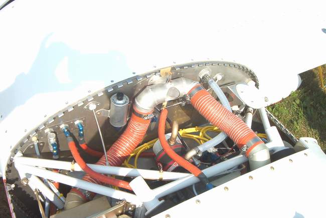
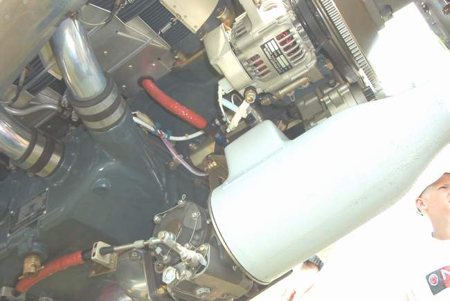
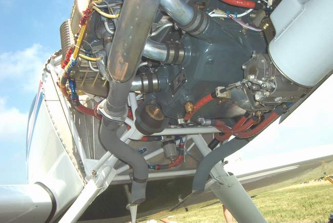
 7-21-04: I didn't want my oil cooler robbing air from the rear cylinders, so I
mounted it in the middle. This was possible because I don't have a vacuum
pump or a tach cable in the way. This also allows easier access to the
back of the engine since the cooler is relatively high up and not cluttering up
the space behind one of the cylinders. More on this later as I'm
still working on it.
7-21-04: I didn't want my oil cooler robbing air from the rear cylinders, so I
mounted it in the middle. This was possible because I don't have a vacuum
pump or a tach cable in the way. This also allows easier access to the
back of the engine since the cooler is relatively high up and not cluttering up
the space behind one of the cylinders. More on this later as I'm
still working on it.
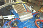
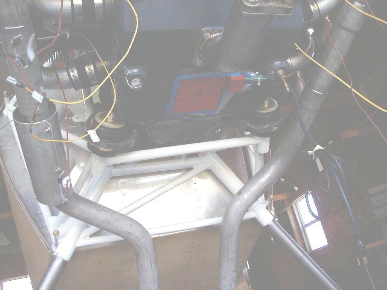
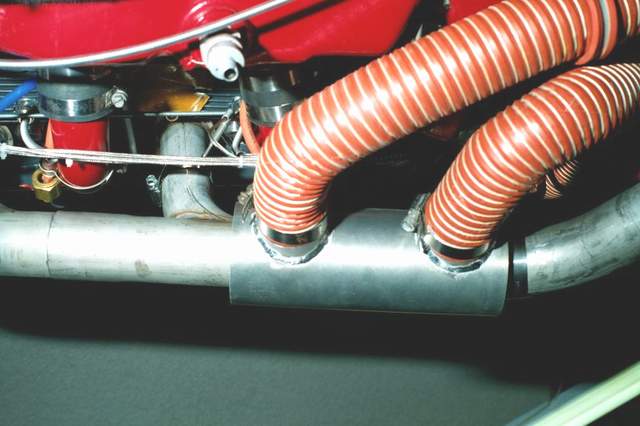
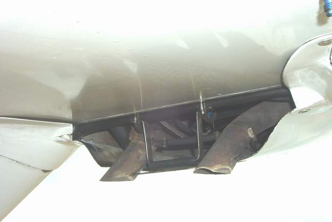
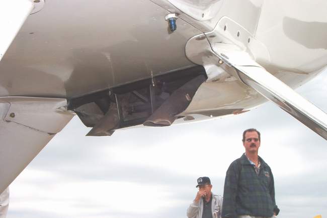
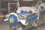
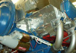
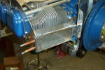
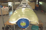
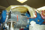
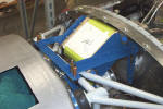
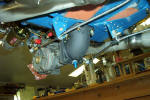
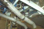
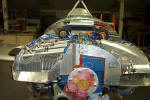
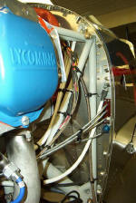
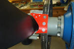
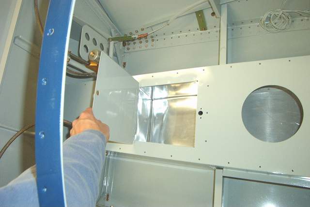
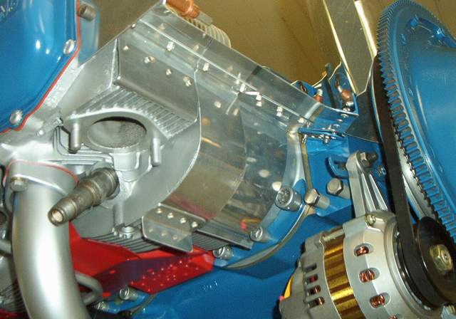
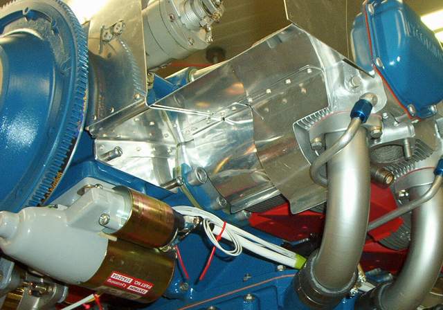
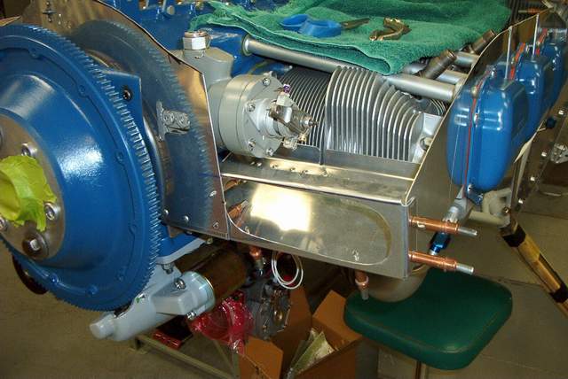
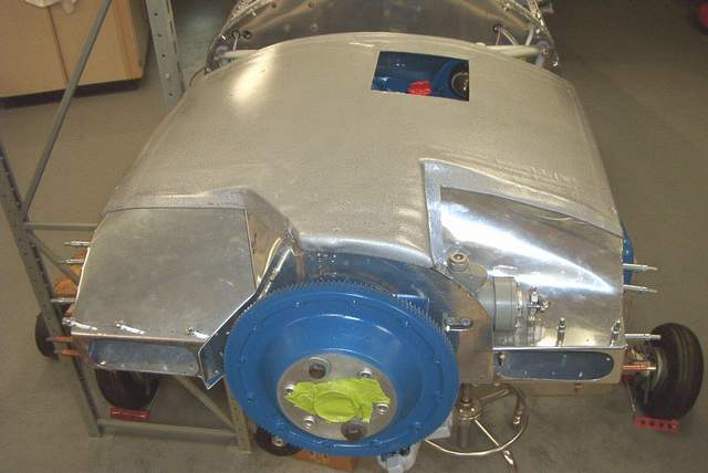
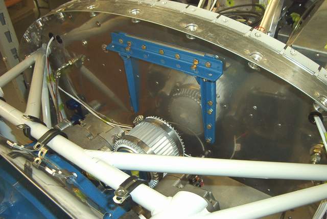
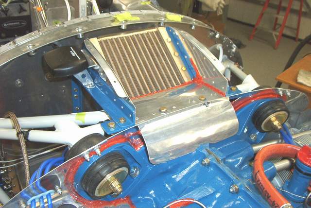
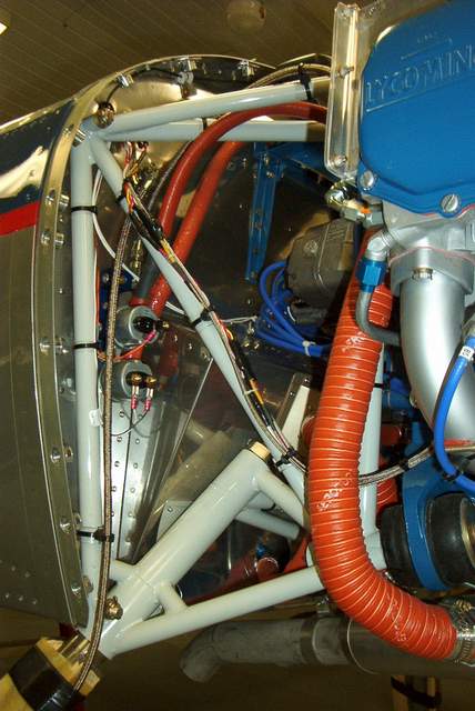
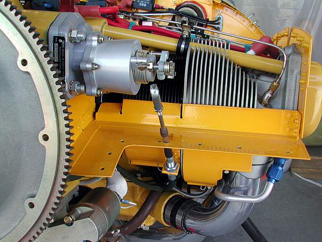
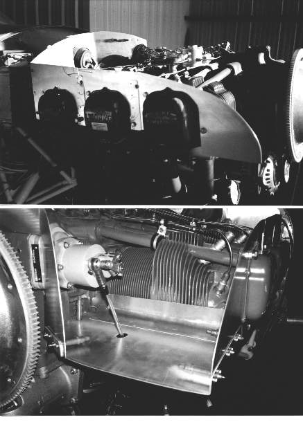
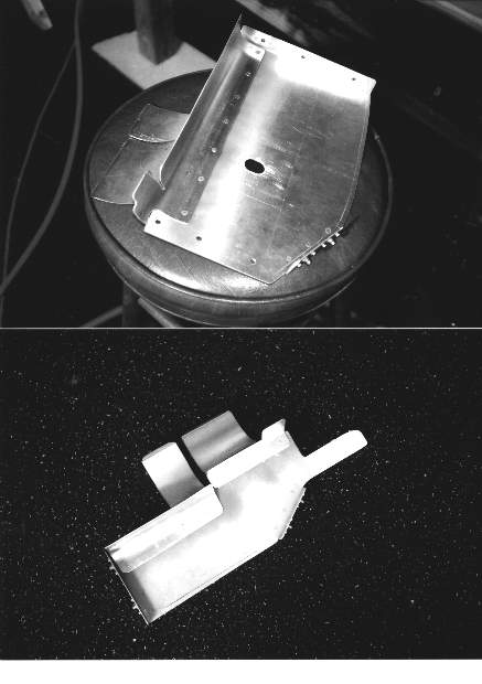
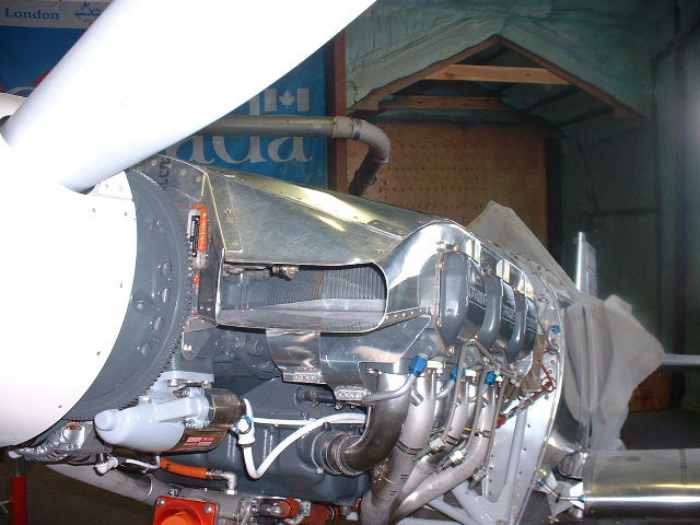
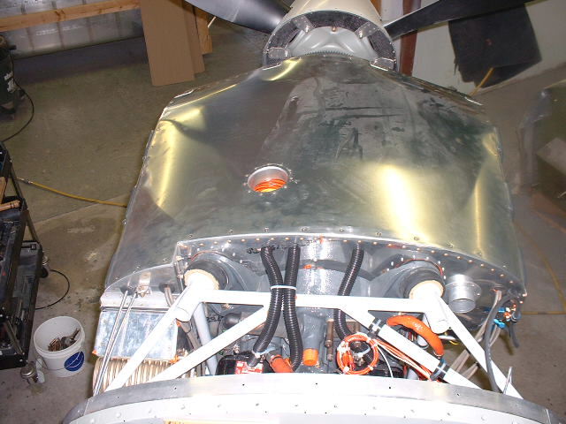
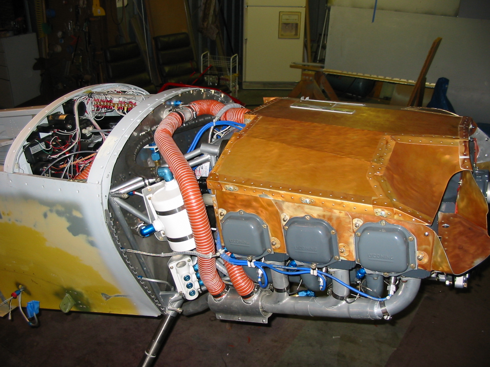
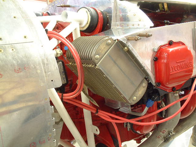
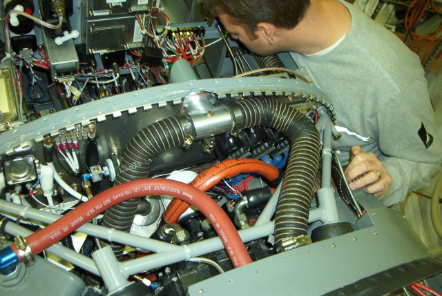
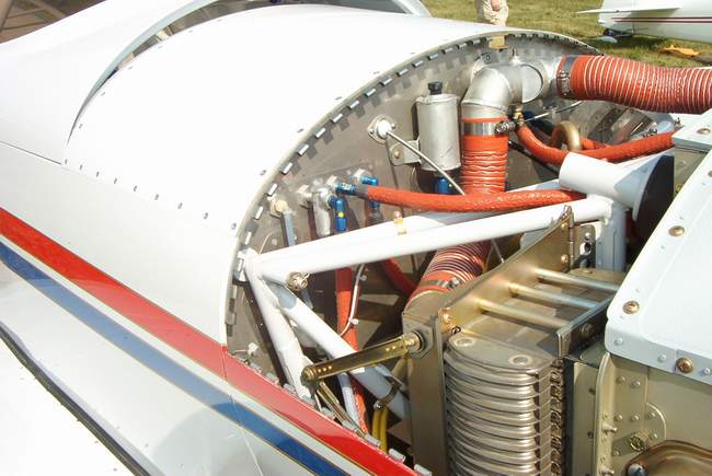
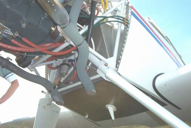
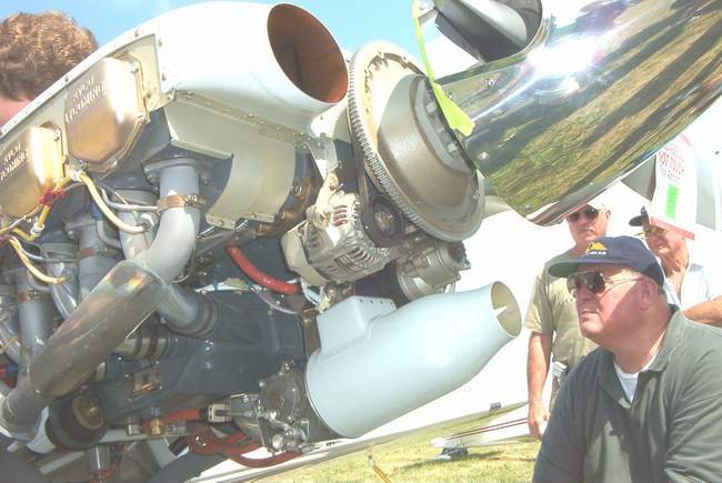
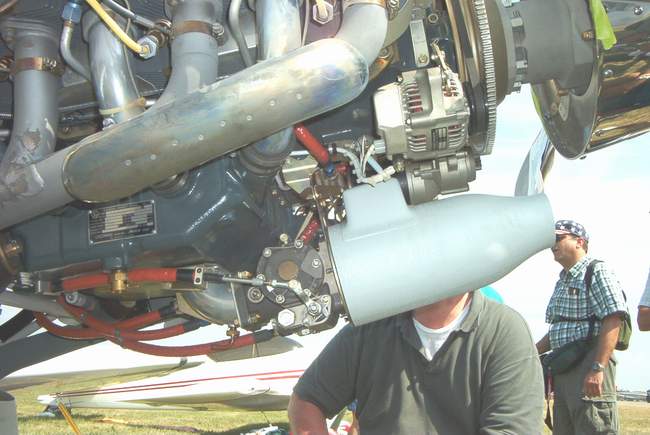
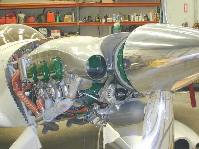
 8-19-04: Here's a shot of the completed cooler setup.
The plan calls for the air to smoothly enter the ramp into the cooler plenum,
move through the cooler, then blow past the Cool Collar that shrouds the oil
filter. The ramp is made to be flexible when the engine moves
around. He he he....what could possibly go wrong??? Bwaaa ha ha ha ha!
8-19-04: Here's a shot of the completed cooler setup.
The plan calls for the air to smoothly enter the ramp into the cooler plenum,
move through the cooler, then blow past the Cool Collar that shrouds the oil
filter. The ramp is made to be flexible when the engine moves
around. He he he....what could possibly go wrong??? Bwaaa ha ha ha ha!
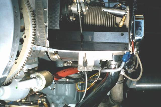
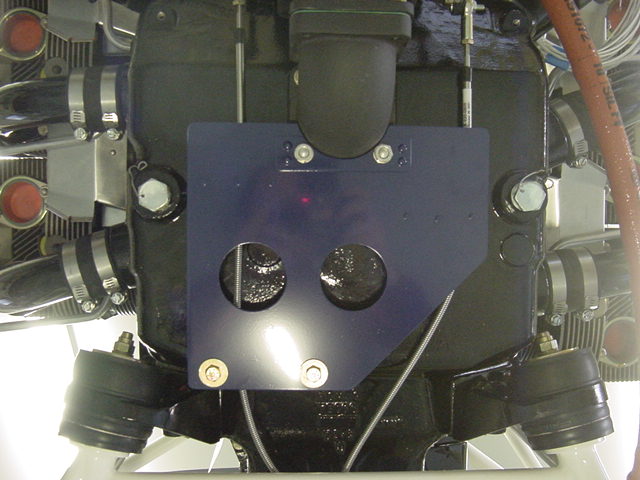
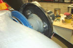
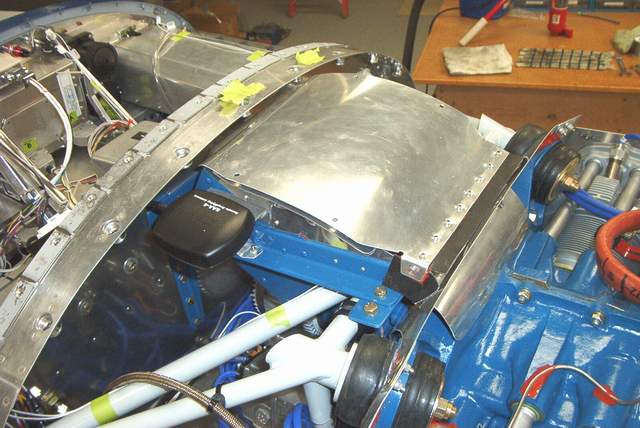
The second photo shows the cover setting in place but not
screwed down. The front edge of the cover is made from cowl baffle
material since the oil cooler and the engine need to move independently.
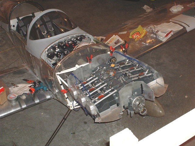
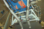
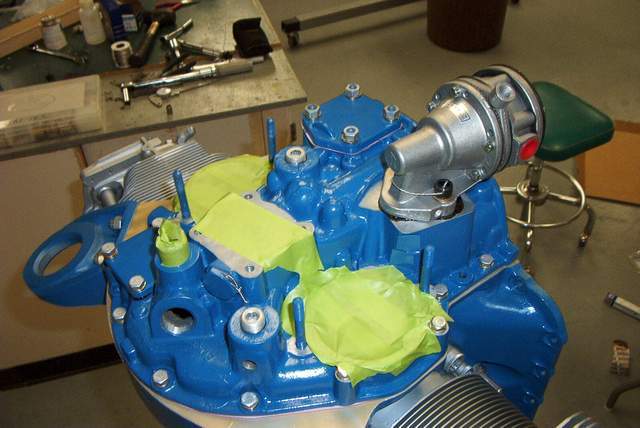
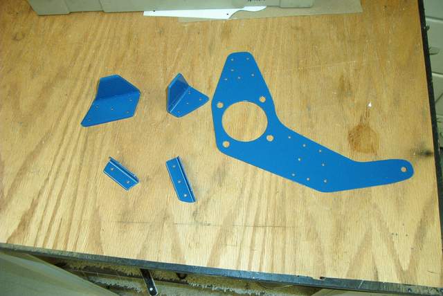
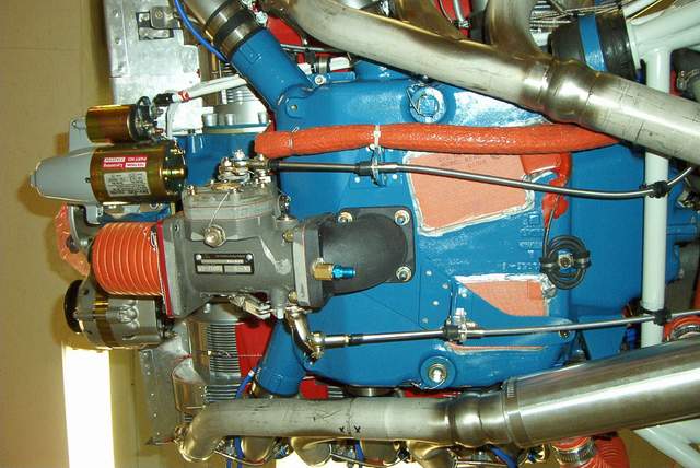
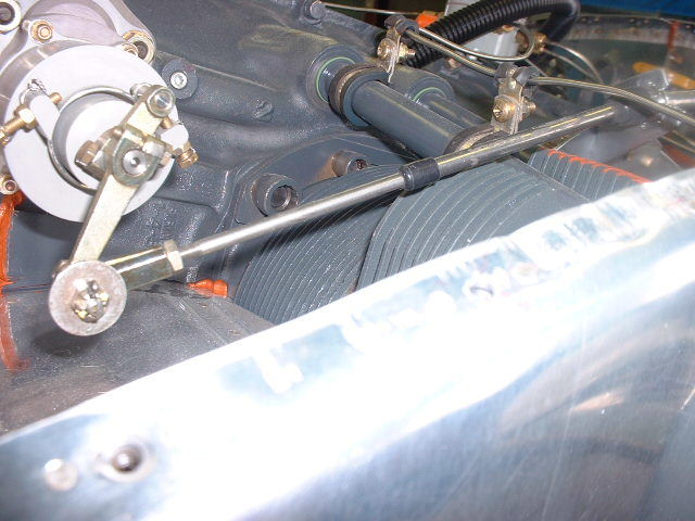
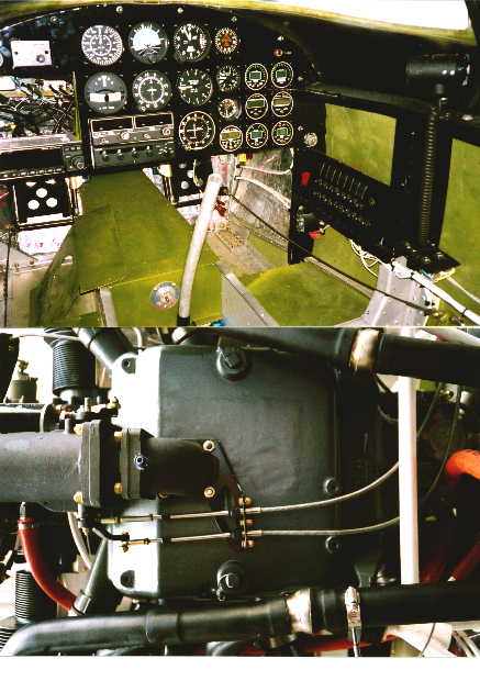
Fuel injection:
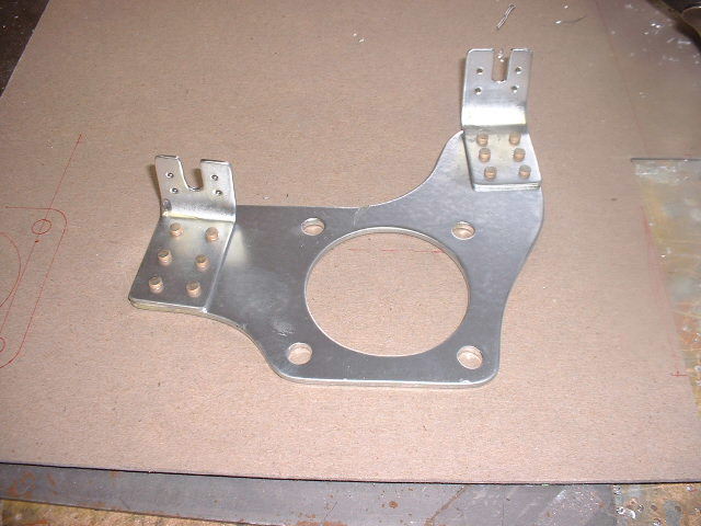
 7-21-04: Bits of the throttle/mixture cable bracket.
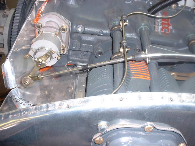
 The bracket installed! Woo hooo! It works.
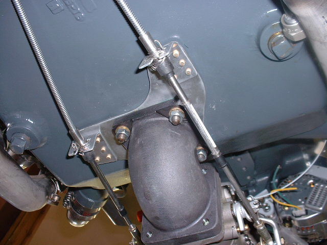
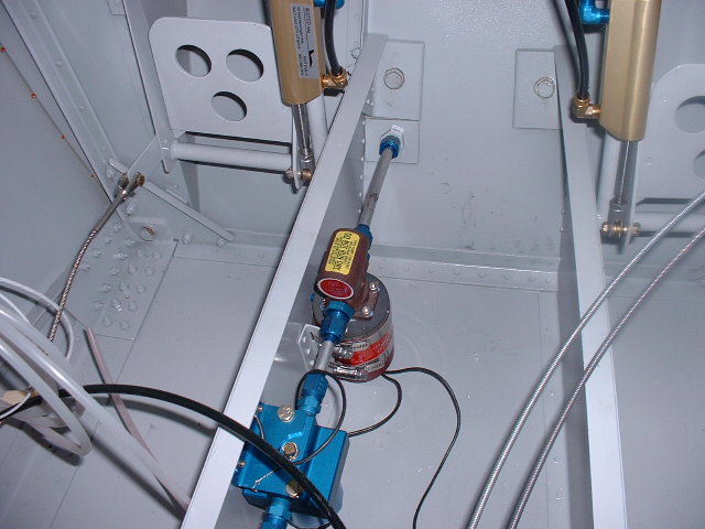
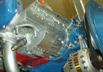
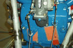
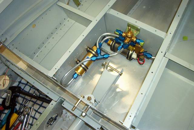
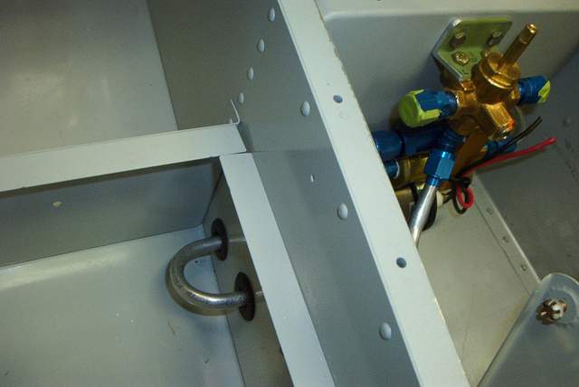
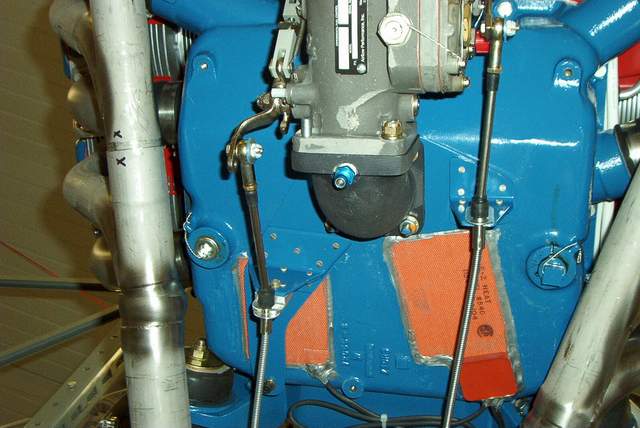
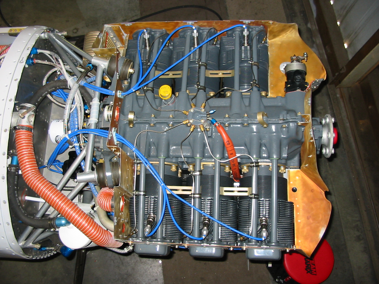
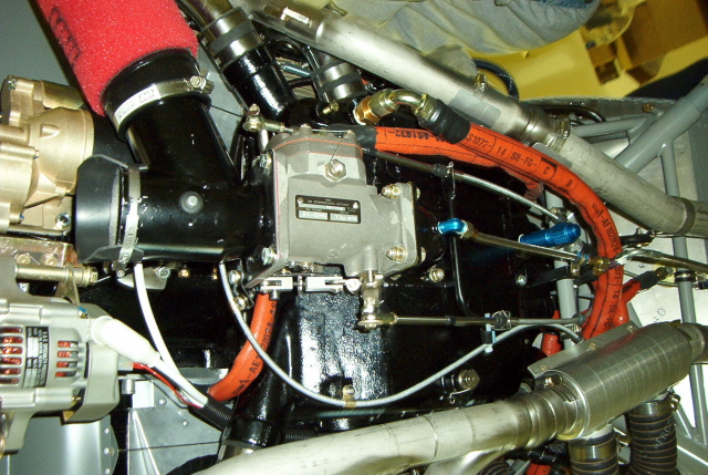
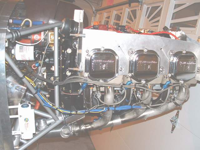
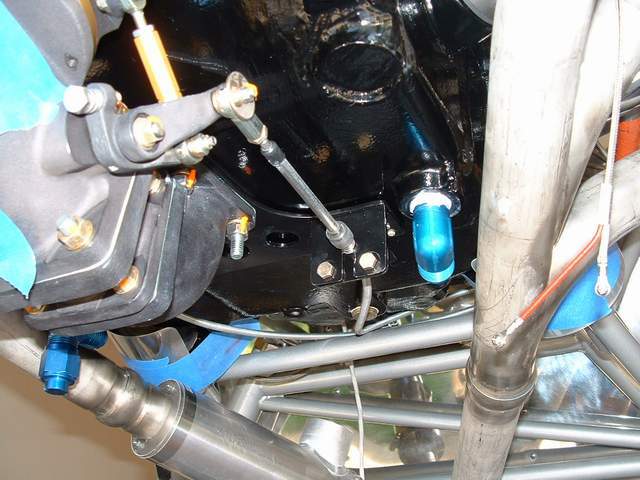
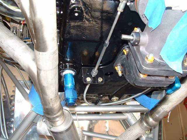
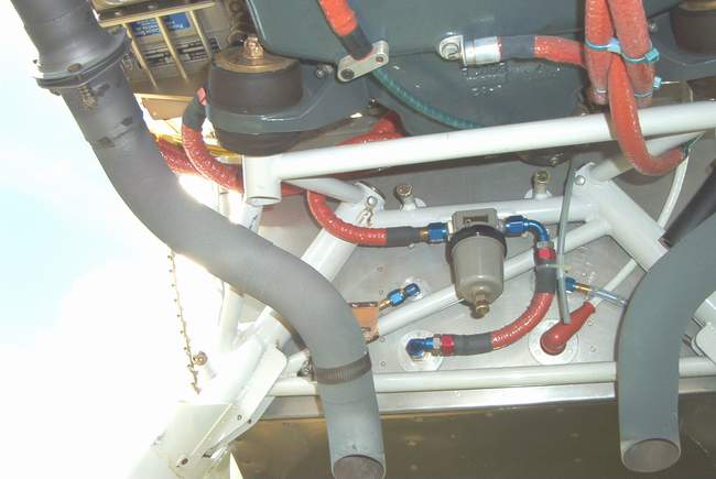
 The flow divider was a bit of a problem to mount. Apparently the flow
divider bracket that I have was intended for a Lycoming with a bolt hole boss in
the side of the case. There seemed to to be nowhere to bolt the darned
thing on! I had to fabricate a new flow divider mount, as seen here.
The flow divider was a bit of a problem to mount. Apparently the flow
divider bracket that I have was intended for a Lycoming with a bolt hole boss in
the side of the case. There seemed to to be nowhere to bolt the darned
thing on! I had to fabricate a new flow divider mount, as seen here.
The original mount was to be offset to the right while the new
mount was designed to mount on the engine centerline. This meant that some
of the brand new injector lines were too short. I had to order two new
lines.
I probably went overboard on the "anti-vibration" silicone RTV
near the flow divider, but since one Rocket crash was attributed to the fatigue
if one of these lines, I feel better about it.
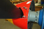
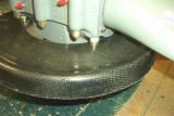
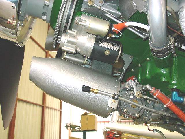
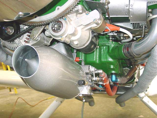
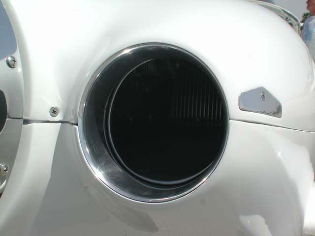
 I noticed on Mark Frederick's new F-1 that he had a nice rolled edge on the
outlet for his cooling air. He said it helped the cooling. Although
I had intended to put one on there anyway, his comments sealed the decision.
Should reduce drag too. We'll see! I made my
"flow-smoother-outer/drag-reducer" from .016" aluminum. Very easy to do.
I added a cover for the fuel line hole after the fuel line was installed.
I noticed on Mark Frederick's new F-1 that he had a nice rolled edge on the
outlet for his cooling air. He said it helped the cooling. Although
I had intended to put one on there anyway, his comments sealed the decision.
Should reduce drag too. We'll see! I made my
"flow-smoother-outer/drag-reducer" from .016" aluminum. Very easy to do.
I added a cover for the fuel line hole after the fuel line was installed.

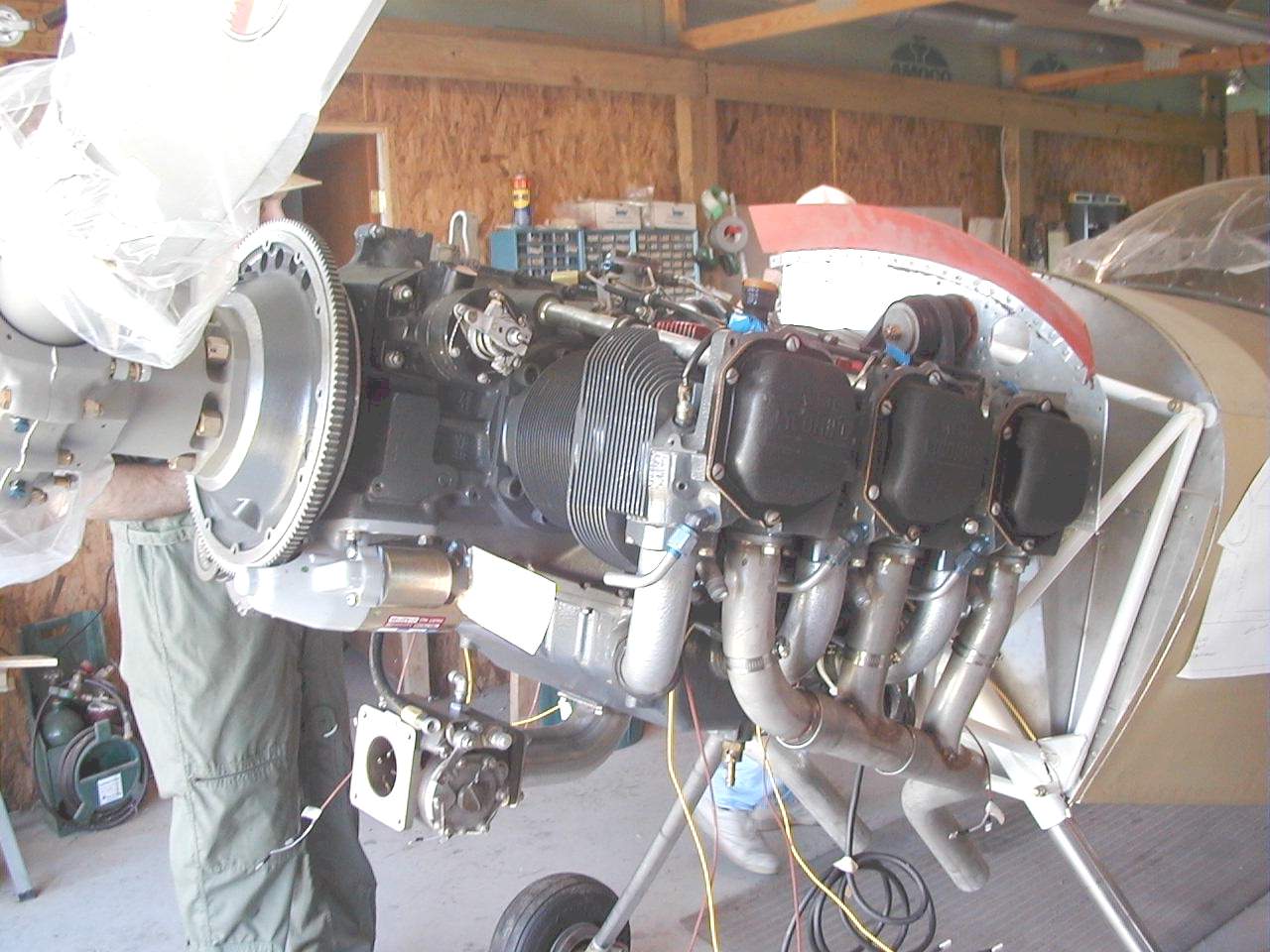
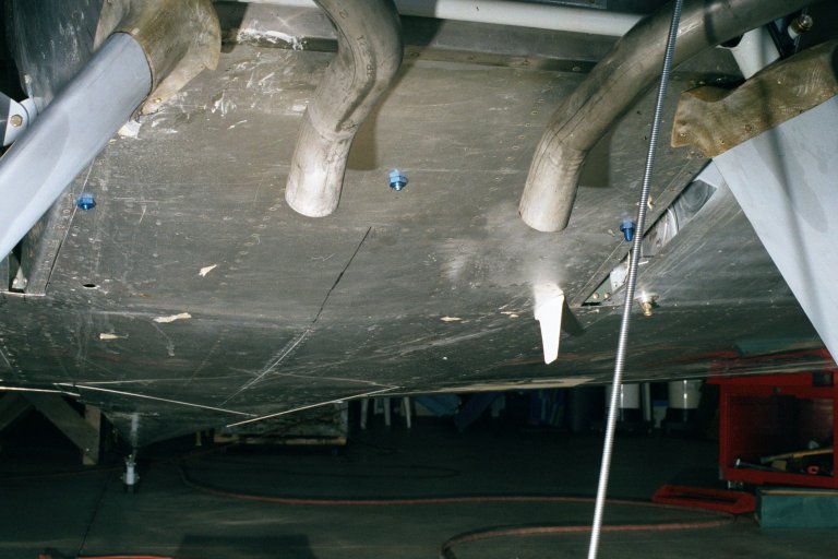
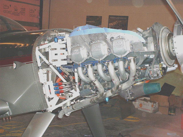
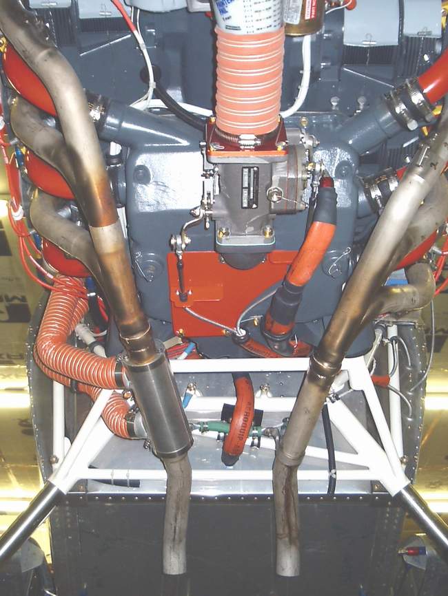
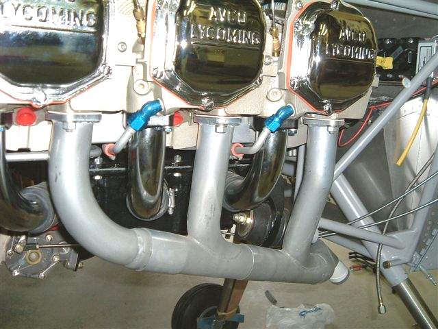
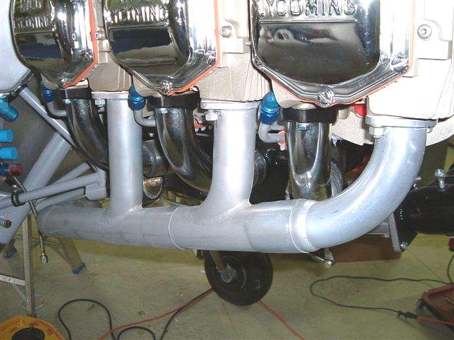
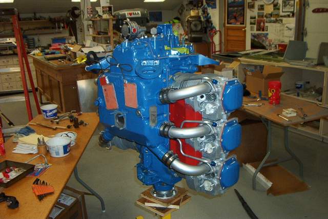
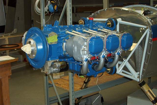
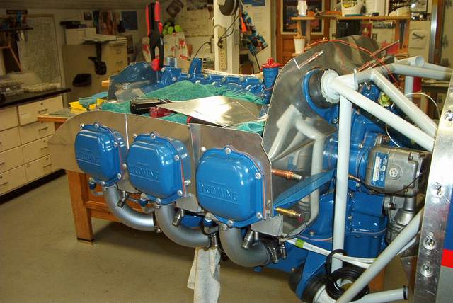
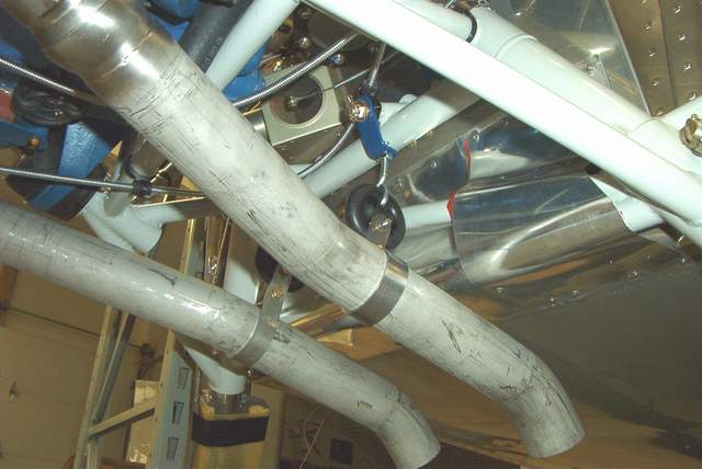
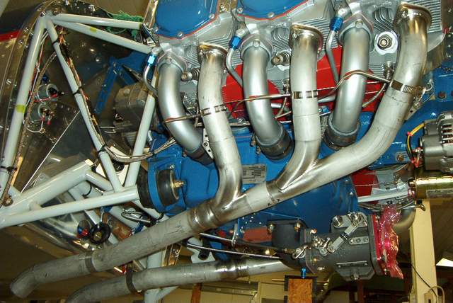
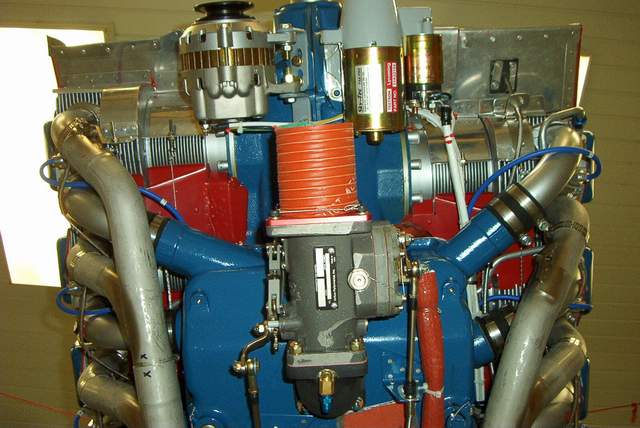
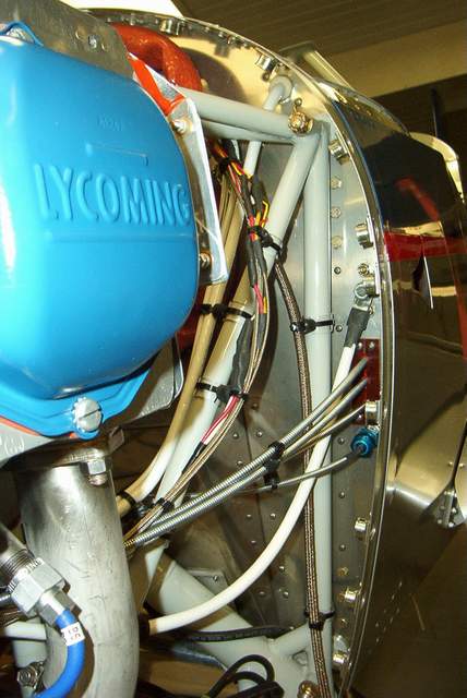
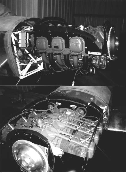
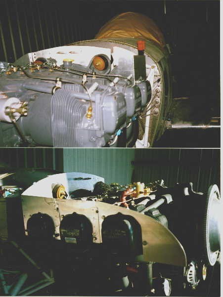
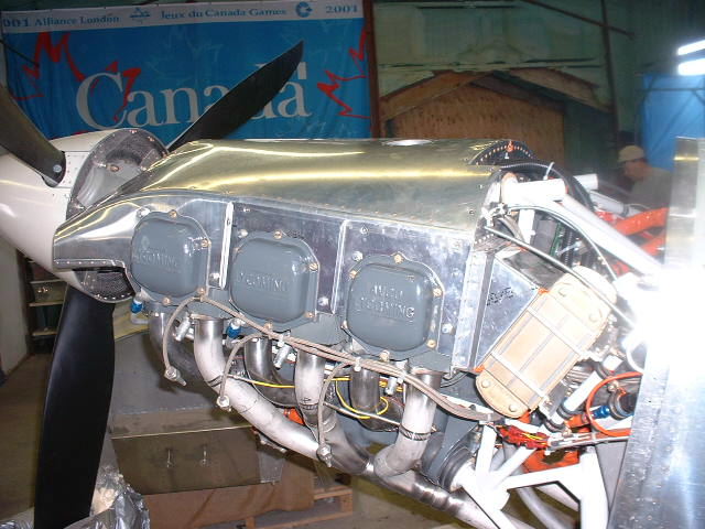
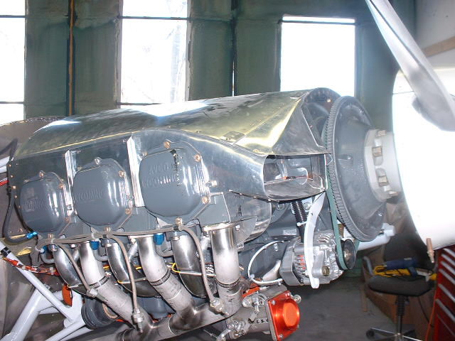
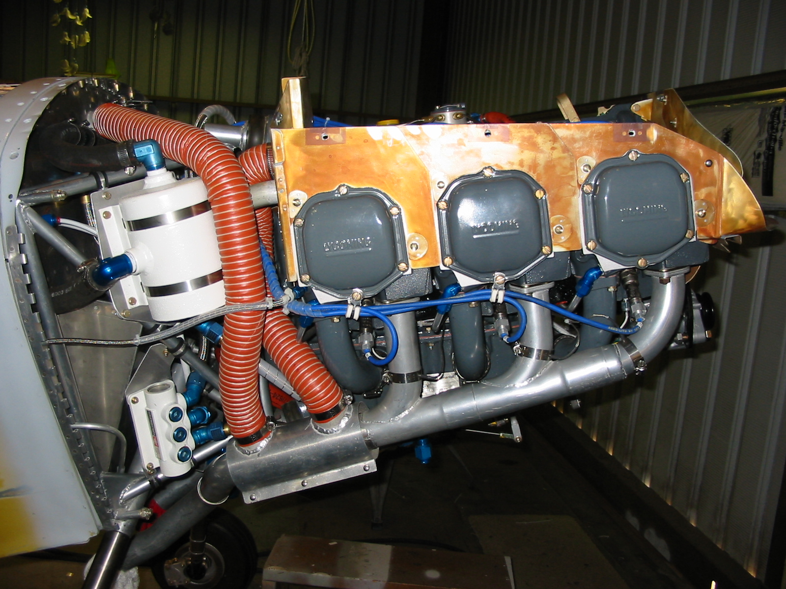
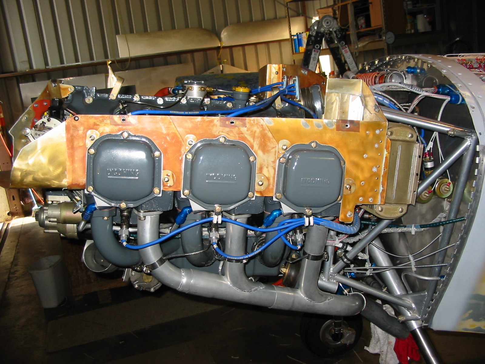
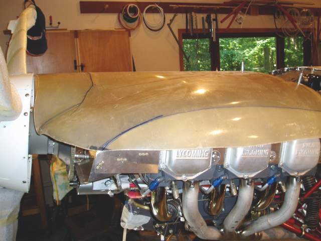
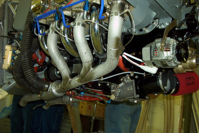
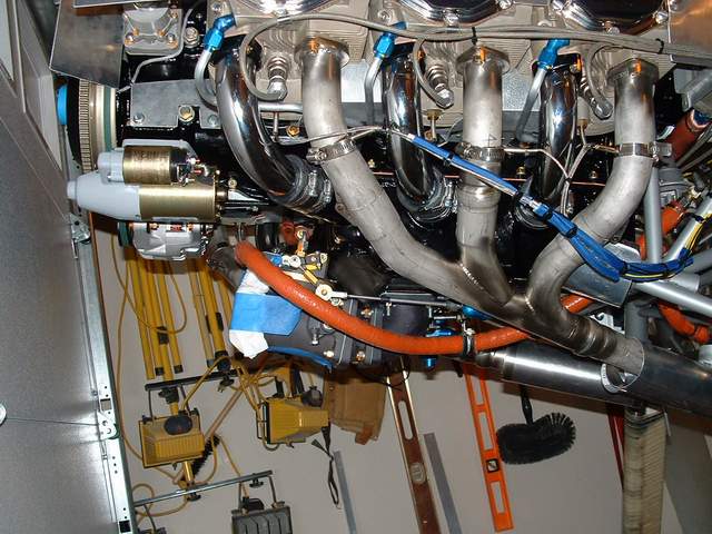
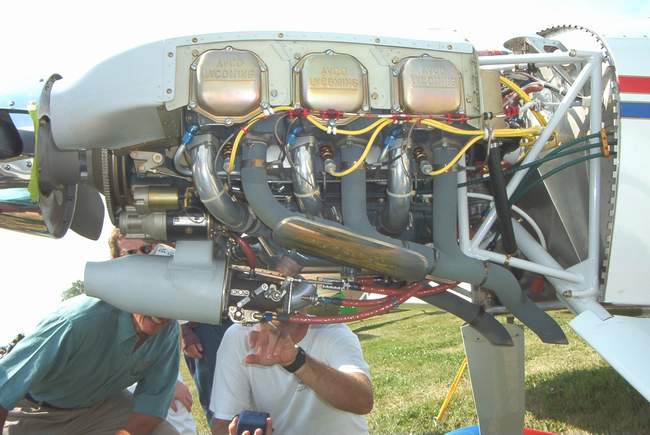
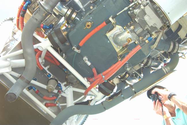
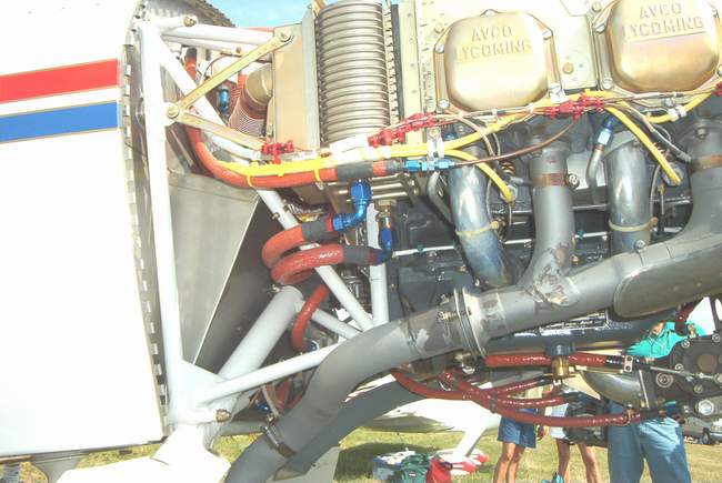
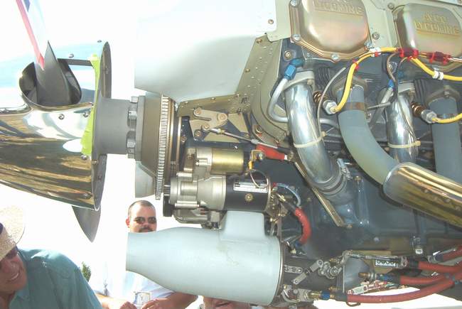
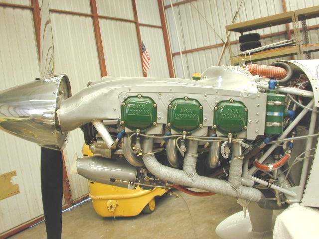
 Shown here and in the photos above is the Vetterman exhaust installation.
His stuff is great. It's one of the VERY few items that you can buy and
actually bolt it on WITHOUT any modifications. Takes about an hour or two,
including the hangers and EGT probes. You do have to drill the holes for
the EGTs. I installed my EGT probes 4.5" from the exhaust flange so
they would all be in a straight section of the pipe... or close. This
seemed like a good compromise as there is no perfect spot.
Shown here and in the photos above is the Vetterman exhaust installation.
His stuff is great. It's one of the VERY few items that you can buy and
actually bolt it on WITHOUT any modifications. Takes about an hour or two,
including the hangers and EGT probes. You do have to drill the holes for
the EGTs. I installed my EGT probes 4.5" from the exhaust flange so
they would all be in a straight section of the pipe... or close. This
seemed like a good compromise as there is no perfect spot.
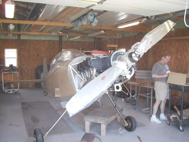
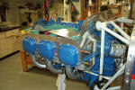
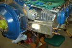
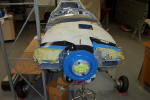
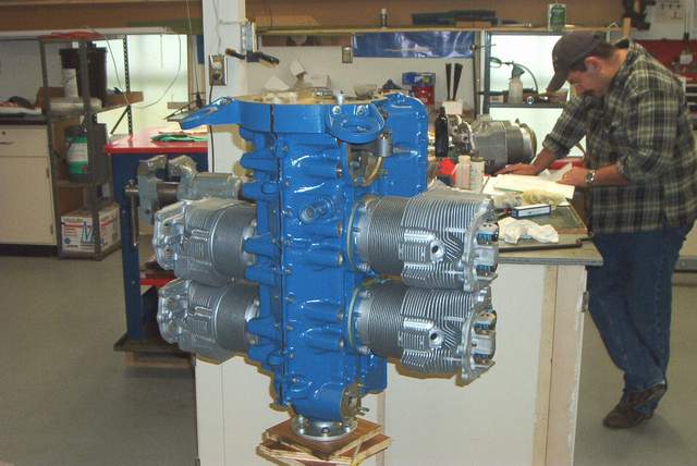
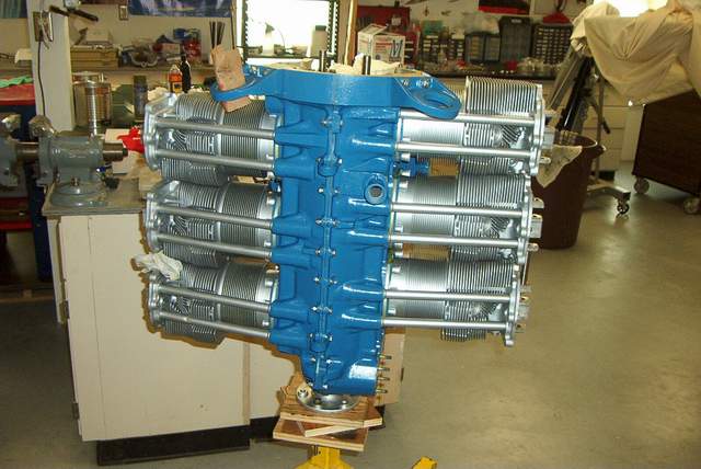
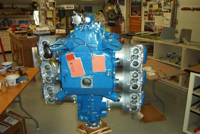
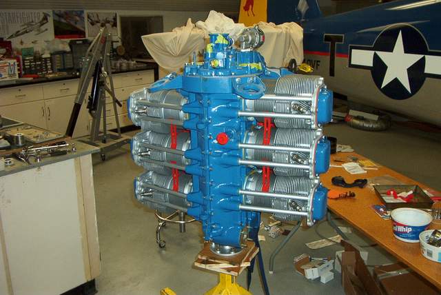
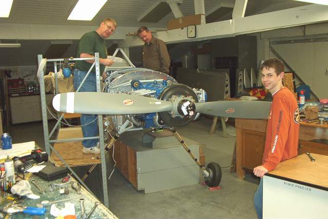
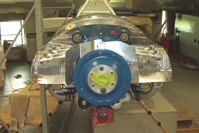
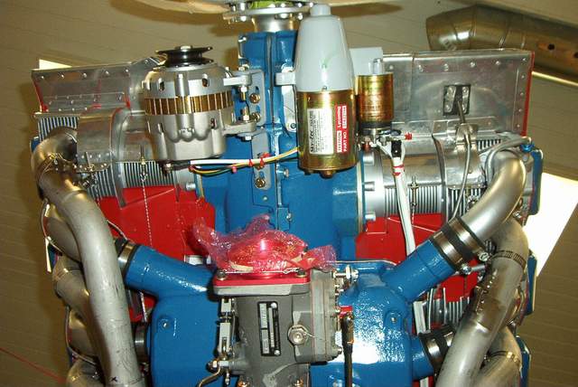
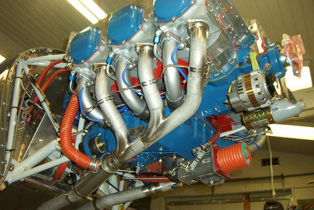
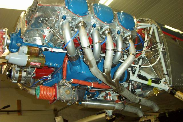
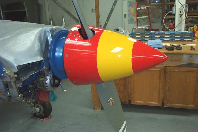
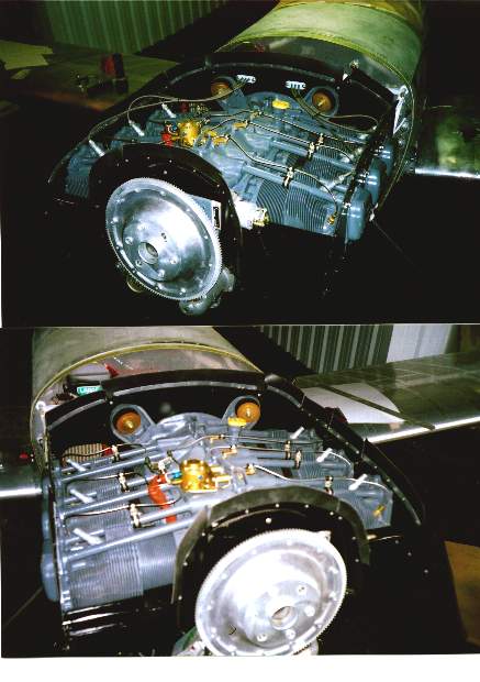
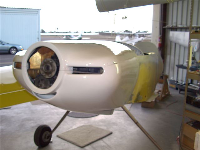
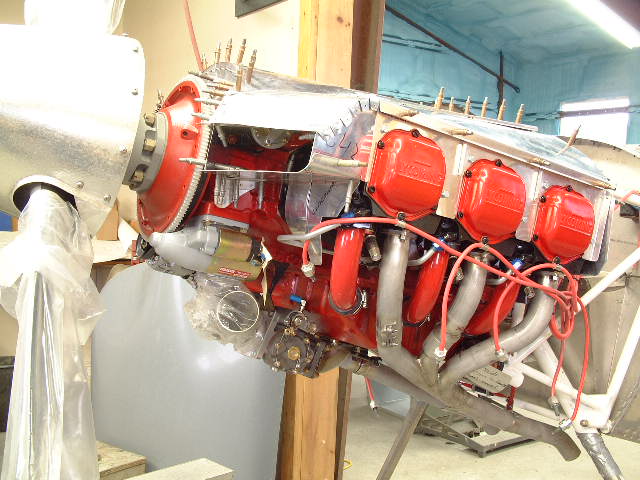
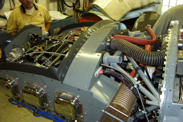
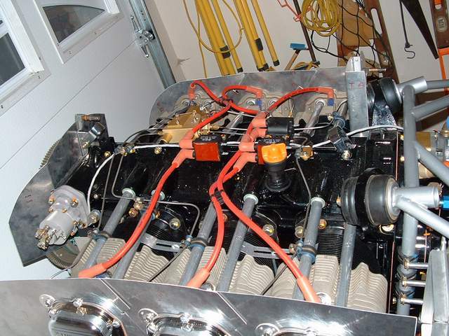
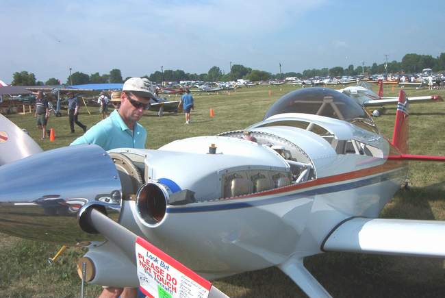
Completed engine (Well 99.9%
anyway) photos:

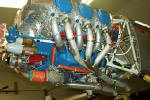


9-10-04: Well, I think that the engine is ready to go to
the airport. There's still work to be done, of course, but it's minor stuff like
making heat shields for the exhaust, timing the mags, and checking fuel flows.
Overall, I am quite pleased with the way everything went together, even though
my baffles and plenum are some of the ugliest work on the entire plane.
Heck, they're not that bad, just not as professional looking as I would like
them to be.
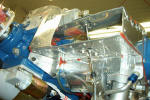
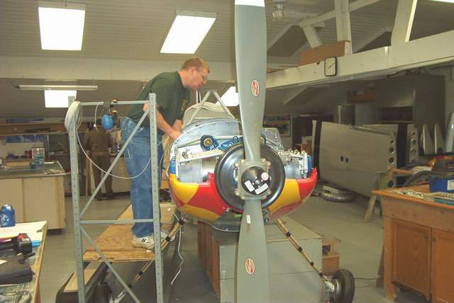
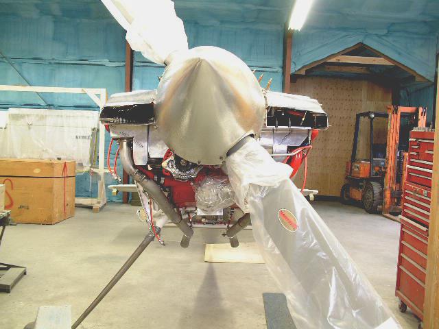
Even if the plenum is not a "10" it looks like it should do its
job nicely. I am pleased with the look of the inlets and outlet.
They "look" like they should flow air with minimal turbulence. Time will
tell!!
The oil cooler still needs an airflow control gate of some sort,
but I'm not going to waste any effort on that until it proves that it can cool
the oil! IMHO, having the oil cooler mounted in the center makes
access to the back of the engine a breeze. I am quite pleased with this
location... assuming that the oil cools properly. At least one person who
seems to be knowledgeable assured me that the center location was a good choice
since it doesn't rob cooling air from a single cylinder. Cool. That
was one reason I chose the center location.
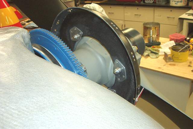
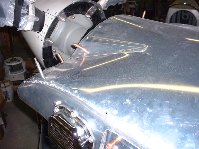
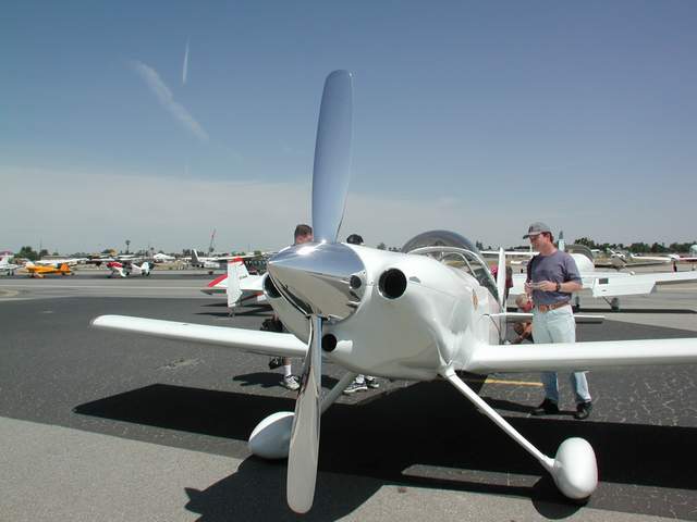
Prop:
9-17-04:
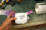
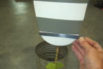
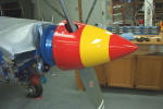
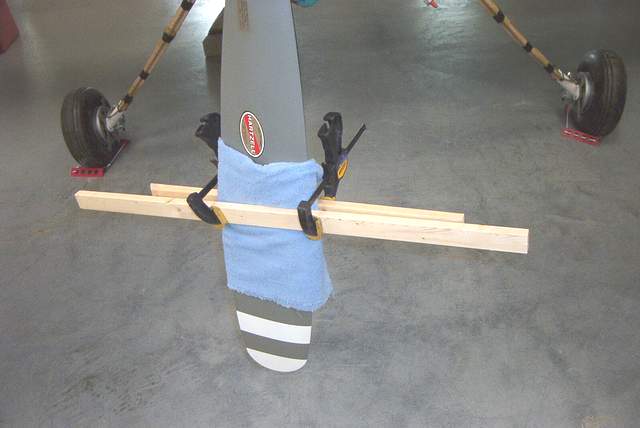
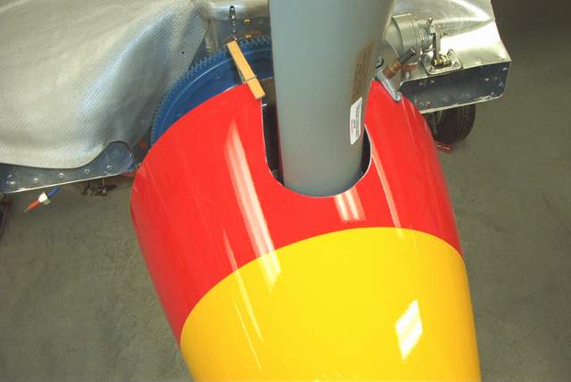
You need to check the blade tracking even on a zillion dollar new prop.
The round ends of the blades make it more difficult to "eyeball" the same spot
on each blade, hence the ruler. The blades should track to within an 1/8"
of each other... or less.
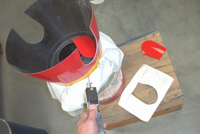
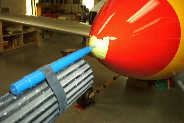
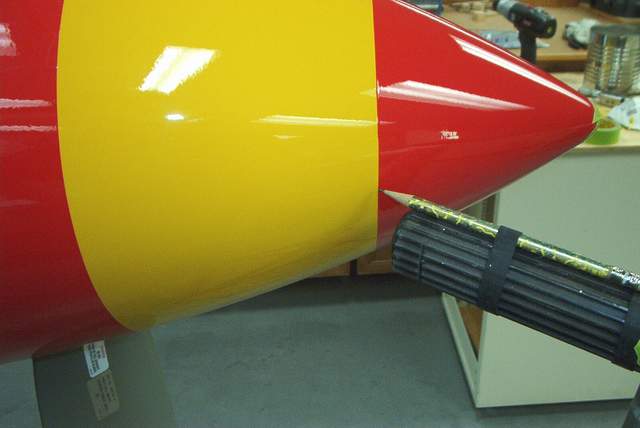
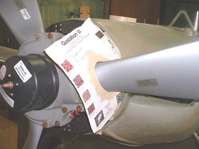
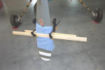 I used Mark's spinner cutout template to mark the blade holes. As you can
see in the pictures below, the aft end of the cutout is narrower than the
blade. This means that you need to twist the blades to install the
spinner. It's difficult to turn the blades, hold them in coarse pitch,
and install the spinner with only two hands. The boards clamped to the
blade allowed me to put my calf behind the blade and hold them in coarse pitch
while my hands installed the spinner.
I used Mark's spinner cutout template to mark the blade holes. As you can
see in the pictures below, the aft end of the cutout is narrower than the
blade. This means that you need to twist the blades to install the
spinner. It's difficult to turn the blades, hold them in coarse pitch,
and install the spinner with only two hands. The boards clamped to the
blade allowed me to put my calf behind the blade and hold them in coarse pitch
while my hands installed the spinner.
 An airsaw makes a nice cut, even on parts that are already painted. Yeah,
I had to sand the rough edge, but it looks fine to me. (I did all of the
painting last September before the cold winter weather arrived. You can't
let the fear of a few scratches stand in the way of progress. Actually,
if you use decent paint and are careful, you won't scratch anything anyway.
I didn't. Really, no scratches anywhere.)
An airsaw makes a nice cut, even on parts that are already painted. Yeah,
I had to sand the rough edge, but it looks fine to me. (I did all of the
painting last September before the cold winter weather arrived. You can't
let the fear of a few scratches stand in the way of progress. Actually,
if you use decent paint and are careful, you won't scratch anything anyway.
I didn't. Really, no scratches anywhere.)
 The rough cutout. The hard part is putting the other one EXACTLY 180
degrees away.
The rough cutout. The hard part is putting the other one EXACTLY 180
degrees away.
 Checking the spinner for wobble. The pen should make a dot, not a circle!
The hub of my prop required three layers of UHMW tape to remove the slack where
the spinner slips over the hub. Make sure that your spinner doesn't
wobble!!! Do this before you add the screw holes to the
backplate!!! NO WOBBLE ALLOWED!
Checking the spinner for wobble. The pen should make a dot, not a circle!
The hub of my prop required three layers of UHMW tape to remove the slack where
the spinner slips over the hub. Make sure that your spinner doesn't
wobble!!! Do this before you add the screw holes to the
backplate!!! NO WOBBLE ALLOWED!
 Since I had striped my spinner, I checked their track too. What do you
know, they were right on.
Since I had striped my spinner, I checked their track too. What do you
know, they were right on.
 You gotta fill in the gap with the piece that you took out. Well, you
don't have to fill it in, but it looks much better this way.
You gotta fill in the gap with the piece that you took out. Well, you
don't have to fill it in, but it looks much better this way.
 Here's the gap filling pieces with the JBWELDED doublers. The SOFT
rivets are mainly to hold the parts together while the JBWELD sets.
Here's the gap filling pieces with the JBWELDED doublers. The SOFT
rivets are mainly to hold the parts together while the JBWELD sets.
 Likewise, these parts are then JBWELDED to the backplate. The screws are
there to hold the parts while the JBWELD sets.
Likewise, these parts are then JBWELDED to the backplate. The screws are
there to hold the parts while the JBWELD sets.
 After drilling the spinner for the screws that will hold it to the backplate,
add the nutplates to the backplate. Also in this shot you can see the
rivets that hold the doubler to the backplate near the bolt holes. A
large area washer is also used here.
After drilling the spinner for the screws that will hold it to the backplate,
add the nutplates to the backplate. Also in this shot you can see the
rivets that hold the doubler to the backplate near the bolt holes. A
large area washer is also used here.
 Mark recommends a doubler to strengthen the carbon fiber. Here's one way
to do it. They are also JBWELDED to the backplate, with pop rivets to
pull 'em tight.
Mark recommends a doubler to strengthen the carbon fiber. Here's one way
to do it. They are also JBWELDED to the backplate, with pop rivets to
pull 'em tight.
 If you put a straight edge on the backplate flange you might find that it is
not flat. Use a file to take most of the bumps off. As you can see
in the photo, there is a depressed area right down the center. I chose to
fill it with a strip of 3M fine line tape.
If you put a straight edge on the backplate flange you might find that it is
not flat. Use a file to take most of the bumps off. As you can see
in the photo, there is a depressed area right down the center. I chose to
fill it with a strip of 3M fine line tape.
 Next a strip of 3M masking tape covers the entire area. The idea is that
the tape will smoosh out any other imperfections AND tighten up the fit.
You want that spinner to fit tightly! NO WOBBLE ALLOWED!
Next a strip of 3M masking tape covers the entire area. The idea is that
the tape will smoosh out any other imperfections AND tighten up the fit.
You want that spinner to fit tightly! NO WOBBLE ALLOWED!
 Then you put the screws in and step back to admire your work. I used
countersunk screws and washers for a smoother fit.
Then you put the screws in and step back to admire your work. I used
countersunk screws and washers for a smoother fit.
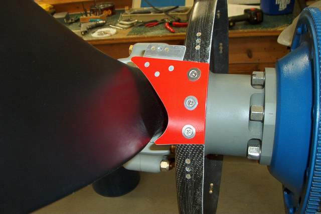
 This shot shows the extra washers needed to space the carbon fiber backplate
away from the prop hub. Mark suggested doing this, although the Hartzell
manual says only 2 washers are allowed. Mine took 4 regular thickness
washers and 1 thin washer to get the backplate to clear the hub.
This shot shows the extra washers needed to space the carbon fiber backplate
away from the prop hub. Mark suggested doing this, although the Hartzell
manual says only 2 washers are allowed. Mine took 4 regular thickness
washers and 1 thin washer to get the backplate to clear the hub.
More on the prop/spinner spacing:
Mark,
I seem to recall that you said that I would need
slightly longer bolts through my prop hub to hold the spinner backplate. Is
that correct? Right now I have 5 washers installed to give 1/32" clearance
between the prop hub and spinner backplate. Does that sound about right?
The AN6-46 bolts that I
purchased for this task are about 0.001" fatter than the bolts that I took
out of the hub. They would go in with persuasion. However, the prop hub
bolts have markings on them that make me suspicious that they aren't regular
AN bolts and I hate to put AN bolts in there without asking someone with a
little more experience here. Vince (THEY
AREN'T REGULAR AN BOLTS! See below.)
Contact Kevin Karam at Hartzell for prop questions -
1-800-942-7767
Cheers
mark
John at Hartzell product support says that
they have a longer bolt, p/n A1584 (5.1" grip length) to replace the bolt, p/n
A3207 (grip length 4.5") that comes in the HC-M2YR-1BF-F8475D-4 prop.
John from Hartzell later called me back
and said that they had a 4.7" long bolt, p/n A-3203 available.
I asked about using AN6-46 bolts instead of
the Hartzell bolts, which look identical. John said he can't officially bless
the use of anything other than their hardware, but he did say that the hub
clamping bolts that hold the spinner backplate do not hold the hub together.
They are there to hold the spinner backplate.
The longer Hartzell bolt is .35" longer than
the AN6-46 bolts that I had. The AN6-46 would be a very tight fit as they
measured 0.001" fatter than the Hartzell bolts. Putting the AN bolts in the
freezer for a few minutes might work... but still a
malletization would be required. The other option is to carve a
relief notch out of the spinner backplate and use the standard bolts. Mark
can chime in on the suitability of doing this.
Vince (Mark says
not to chop up the spinner.)
From: Bob Japundza
Sent: Monday, April 26, 2004 11:14 AM
Subject: RE: prop bolts
Been there done that.
The longer Hartzell bolts were at the time $24.00 apiece. I was told these
bolts are x-rayed, even the new ones. These bolts have a unique marking on
them, made for Hartzell. (IIRC they're stamped with a triangle with an "H" in
the middle).
I don't know how it could be possible that those bolts don't hold both
halves of the hub together, since the shanks of the bolts goes thru both
halves of the hub and they're torqued to the Hartzell spec which is shown in
the overhaul manual which I have a copy of.
Regards,
Bob
I
asked John, the Hartzell guy, about the bolts and their relationship to
holding the blades in. He said that they are to hold the spinner backplate,
not the blades, even though they definitely appear to be in a good spot to
support the blades, IMHO too.
We discussed what would happen if the carbon fiber backplate got crushed, damaged,
melted, termites ate it off, whatever, and he said that would create other
problems (like lots of noise and vibration) but the blades would be remain.
It seems to me that the carbon fiber backplate would be the strength limiting item
in the stack of parts in question. If it fails then the bolt will be loose
and fail anyway.
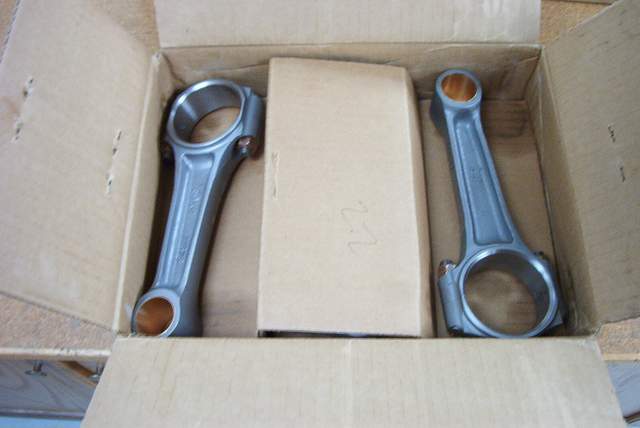
$24 per bolt does seem a bit steep... unless you've recently bought connecting
rod bolts.
Mark did mention, as I remembered from earlier, that trimming the backplate is
not the best idea in his opinion.
I'm just reporting what I was told... hell, I could have been talking to the
Hartzell janitor for all I know.
YMMV
Vince
FWIW, I talked recently about the spinner backplate / hub clamping bolts that
were too short. I've got some more info for those who are using the 2 blade
prop.
I noticed that the torque specified for the Hartzell bolt, 22 footpounds, is
higher than the torque that we would normally put on an AN6 bolt, 16 foot
pounds. Hmmmm.
5-01-04:
Not being all warm and fuzzy about using a non-specified bolt, I decided to
get the proper bolt. I called Hartzell and they don't stock the A-3203 that is
needed. What? I called several other prop shops.. no luck. Finally, Ottosen
Propeller in Phoenix, AZ had them in stock. You can call them at 1-800-528-755.
They are $38 each.
Then in a fit of curiosity, I decided to see what I was getting for $38 each.
I took one of the short hub bolts that I can't use, actually I took all 4 of
them, down to the engineering materials lab. It is in this lab where metal meets
its doom. Not content to destroy only $38 bolts, I also grabbed a couple AN
bolts, and a couple old Van's prop hub bolts. If you've built an RV with a wood
prop you'll remember the 6.5" bolts that hold the prop on.
The tensile testing is fun. Lots of non-action followed by "BANG" as the bolt
breaks. Of course, you can stop the test when the bolt silently yields�.but what
fun would that be?
Results:
# bolt type
diameter
Brinell hardness
tensile strength (raw number)
PSI (if I calculated correctly)
1 Hartzell A3207 . 3705
201
17500
162,000
2 Hartzell A3207 . 3705
201
3 AN6
.3725
201
15000
137,000
4 AN6
.3725
197
5 RV-prop
.3725
174
14200
130,000
6 RV-prop
.3725
192
What does all of this mean? Is the extra tensile strength worth $38 each?
Who knows? Besides I only tested one sample and have no idea what the
variability is. It's just for grins.
YMMV,
Vince
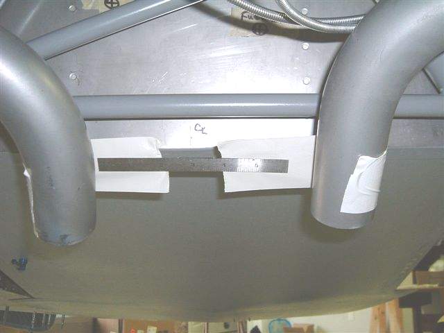
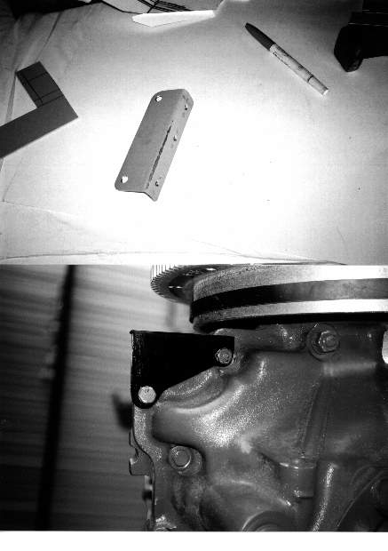
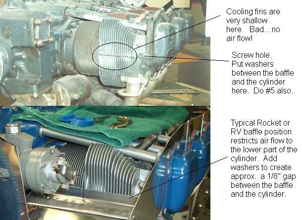 It turns out that the front of the #2 cylinder and the back of the #5 cylinder
(#3 on 4-cylinder engines)
have very shallow fins. This is fine for the other 4 cylinder positions...
they've got plenty of air flowing past them due to the way the engine is put
together. However, the #2 and 5 cylinders have a design flaw because it is
possible to put the cooling baffle on so tightly that no air can flow past part
of the cylinder. Wow... that isn't good so fix it as described in the
photo. You will be happy and your cylinders will be positively thrilled.
It turns out that the front of the #2 cylinder and the back of the #5 cylinder
(#3 on 4-cylinder engines)
have very shallow fins. This is fine for the other 4 cylinder positions...
they've got plenty of air flowing past them due to the way the engine is put
together. However, the #2 and 5 cylinders have a design flaw because it is
possible to put the cooling baffle on so tightly that no air can flow past part
of the cylinder. Wow... that isn't good so fix it as described in the
photo. You will be happy and your cylinders will be positively thrilled.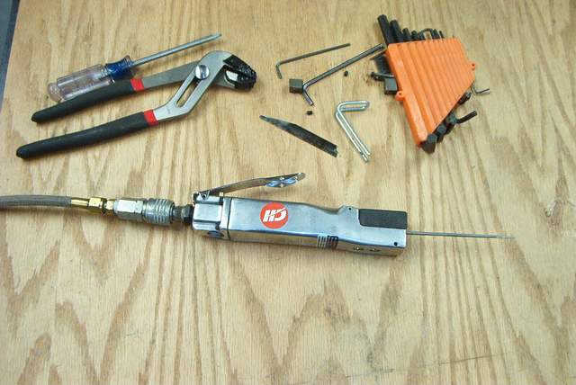


.JPG)
.JPG)