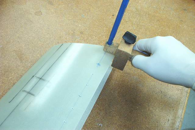
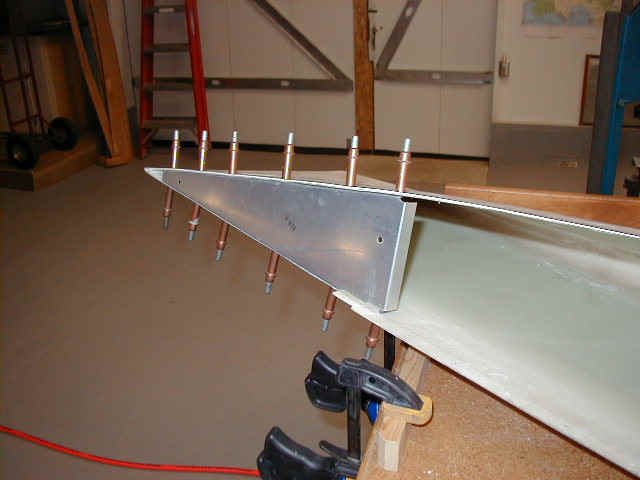
 Someone was talking about marking a line of holes. Sure you can use a
yardstick, but that is so last week. And a yardstick can't mark around the edge
of round parts like spinners, bulkheads, etc... This tool is happening. It's da
bomb.
Someone was talking about marking a line of holes. Sure you can use a
yardstick, but that is so last week. And a yardstick can't mark around the edge
of round parts like spinners, bulkheads, etc... This tool is happening. It's da
bomb.Construction Notes for the tail and wings
The following is a loosely edited collection of items, some from the Rocket list archives, some from other sources, and some from my very own personal building experiences. The presentation of this hodge-podge is not optimal. I tried to place *end of comment* between each comment so it would be easier to read.
Many of the topics are covered extensively on many on the RV building sites. Be sure to check them also.
Some good info, but beware, some junk too!!! You be the judge!
One thing you should always do is to make liberal use of a BIG BLACK MARKER. Use it to label parts on all sides with "TOP", "LEFT", "RIGHT", etc. It will save you gobs of money. Another thing many builders do is to get in a big hurry to trim the edges of everything to match the drawings. Try to imagine if you'll need that metal to obtain a better fit later when you're putting subassemblies together. Remember that these things are hand-built and the interchangeable parts concept does not apply to these airframes, so trim everything with getting the best fit in mind. Vince Frazier *end of comment*
Markers for layout use on aluminum:
I switched over to Pilot brand pens about 15 years ago because the Sharpie brand is inferior, IMHO. I like the Ultra fine point Pilot markers, blue color shows up best on aluminum to me, and I can use one for months if I'm careful. I just ordered a box from the link below. 12 markers for $15.... I'll take it. They are difficult to find in stores since most major retailers are locked up with the Sharpie brand name.
If you get in a jam, you can pull the top off these pens and add one or two drops of isopropyl (rubbing) alcohol and use them for awhile longer.
For best results and longest life, don't smash the tips. Personally, I don't let anyone else use my markers. Most guys are ham fisted apes and the first thing they do is press harder when the ink isn't flowing. That doesn't work, but wiping the dirt and oils off the aluminum does. Then you can write easily.
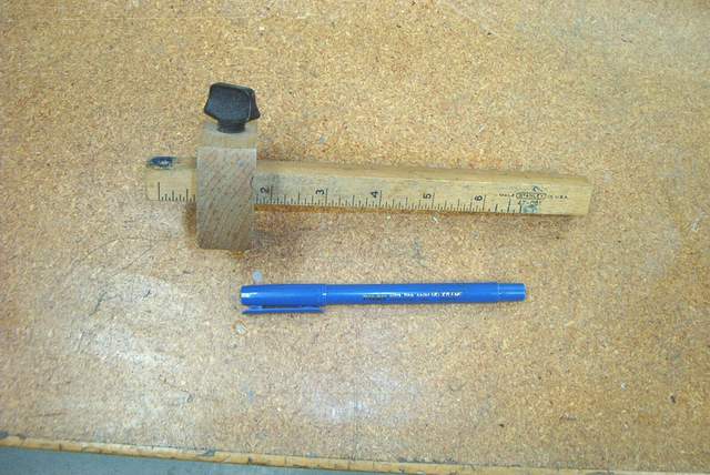
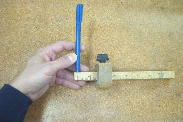
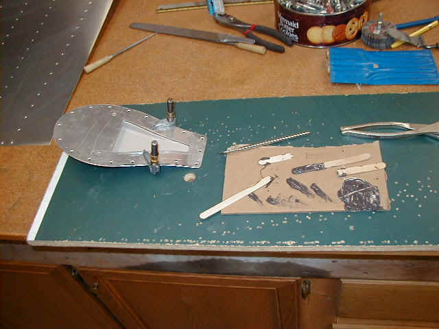
BTW, a marking gauge from Home Depot or Lowe's can be drilled out to accommodate these markers and your edge marking and layout chores will be 99% easier.
http://www.pilot-pens.com/ homepage
http://www.pencity.com/cgi-bin/SoftCart.exe/Pilot/ExtraFineMarker.htm?L+scstore+unlr7898+1014064181 takes you straight to the ordering and info for this marker.
On another related note, a local RV-7 builder tried to prime over all of his marker lines. I hope he likes 'em 'cause they will show through forever since the marker ink often bleeds through the paint. Fortunately they're inside and won't show much. He knows now to wipe the ink off before painting. Vince Frazier *end of comment*
Someone was talking about marking a line of holes. Sure you can use a
yardstick, but that is so last week. And a yardstick can't mark around the edge
of round parts like spinners, bulkheads, etc... This tool is happening. It's da
bomb.
Go to any decent woodworking store (or Home Depot, Lowes, etc) and ask for a marking gauge. They come with a steel pin at the "zero" line. Drive it out and toss it. (9-9-04: I can't find these damned things anymore. Make your own. I mean, jeez, it's only a couple pieces of wood!)
Drill the hole as needed to accommodate your favorite FINE LINE MARKER. I use blue Pilot brand markers because blue shows up best on the aluminum. They're hard to find so use FINE LINE Sharpie brand if you need to.
You need this tool! I have drawn miles of lines with mine and wouldn't trade it for a brand new drill press. No lie.
BTW, Avery makes a similar, but crude, device. He also sells the Pilot brand markers. Or order the markers online at www.pencity.com
Vince *end of comment*
Dimpling and Riveting:
Well guys, I had a problem with a rivet today, drilled it out a couple of times now the hole is a little big. I was able to find the rivet that I need to fill the hole but am having difficulty finding a set for my rivet gun that will work. PS. Something like this might show up in this years riveting contest June 23, perhaps Mark will have better luck this year. Tom Martin It's a joke! Don't try this at home. :-)
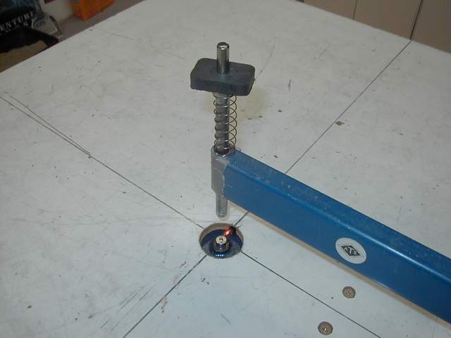
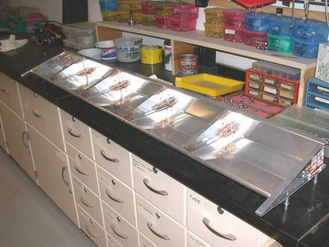
Here's a shot of my dimpling table which was made from one of my RV-4 crates. The top is a slick piece of masonite bathroom paneling which is cheap, white, slick, and easy to keep fairly clean. The lines intersect at the dimple dies which are mounted in one of the C-frame dimplers that you can build or buy.
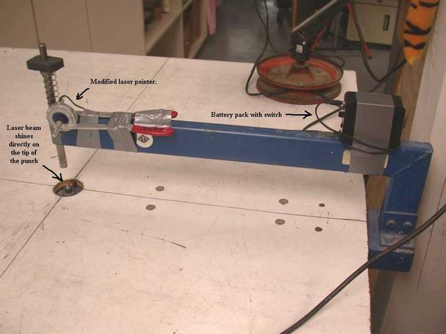
Update: 11/27/2001: My dimpling table is now the coolest one in Posey County, Indiana.... possibly the world. Why? Because I took the time to fashion a truly useful laser pointer accessory for it. The laser points exactly to the tip of the die so I NEVER waste time trying to get find the bloody rivet hole. Less searching around also means far fewer scratches on the precious aluminum. I highly recommend this tool!
Here's the deal.... get a laser pointer from your 12 year old son or buy one from Harbor Freight. The pancake shaped ones are MUCH easier to modify than the bullet shaped ones. You'll very likely ruin the bullet shaped one while trying to disassemble it. The pancake ones have a screw holding the unit together.... much easier to modify.
Disassemble the laser as needed to connect a battery pack and beam attenuator to it. You'll need 4.5 volts to power the laser, so you'll need something to hold three 1.5 volt batteries in series. Components are available at Radio Shack or cannibalize some of your kid's toys. The battery pack will run this laser for days, weeks, or months... I don't know yet because I'm still on the first set of batteries. Hard wire the battery pack into the laser by soldering the wires to the appropriate battery terminal on the laser pc board, bypassing the laser's switch. Put a cheap toggle switch in the battery pack so you can turn the silly thing on and off easily.
You'll definitely need some sort of beam attenuator to decrease the laser beam intensity. Otherwise the intense beam reflecting off of the die and shiny aluminum will hurt your eyes. There are many ways to cut the beam intensity down.... a piece of welding shade lens, a piece cut from an old x-ray film, a filter from the wife's camera bag, etc.... You just need to find a piece of something that will attenuate the beam enough so that you can stare at its reflection comfortably. Of course, you don't want to scatter the beam either so you'll have to scrounge a bit to find something that works. Glue the appropriate beam attenuator in place inside the laser's plastic case on the brass where the laser beam exits. A piece of black electrical tape with a pinhole in it is useful to cut out the scattered light that often results from adding the beam attenuator.
After you get the laser modified it is a simple task to position it on the C-frame dimpler using scraps, clamps, intricately machined fixtures..... or my favorite, the Handyman's Secret Weapon --- DUCT TAPE! *end of comment*
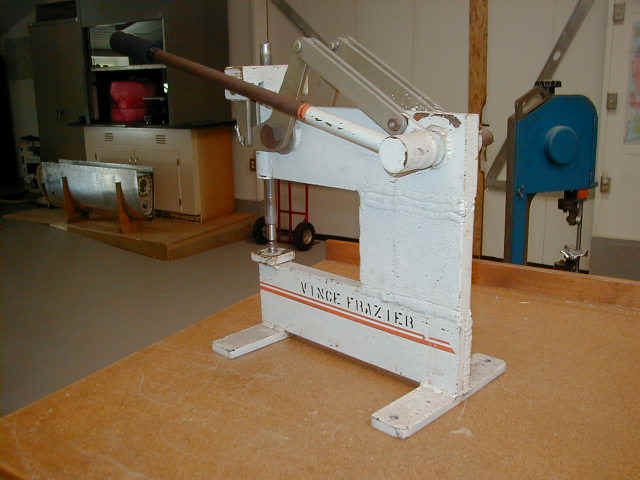
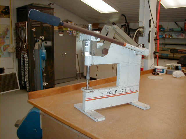
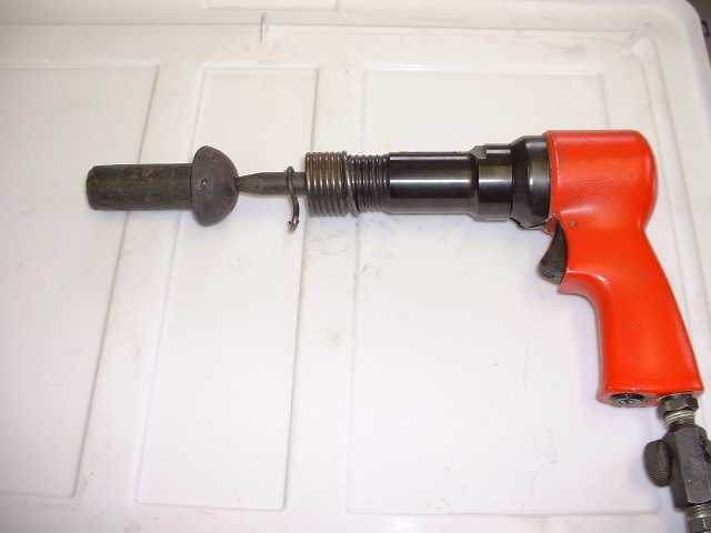
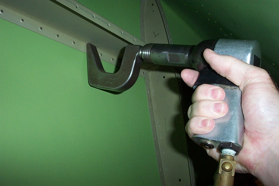
Many, many, years ago, I was lucky enough to buy this one-of-a-kind rivet squeezer from another RV builder. It is stupendously handy AND it will easily smash the big 3/16" spar rivets. Blake sells an equivalent unit on www.flyboyaccessories.com if you're interested. *end of comment*
I always use a swivel set for flush riveting. The kind with a red rubber cup. They are stupendous. Throw your other flush sets away. I highly recommend this tool!
Backriveting is OK, but with one of these swivel sets you can do a comparable job on the wings and fuselage skins. I tried both techniques and saw no difference. Backriveting works great on the control surfaces though. *end of comment*

Hey Guys, Thought I'd share a new toy I have. I believe in backriveting anything I can. The quality is just the best. Not saying that conventional riveting is bad, it can just be a little better. Anyhow, a friend gave me a c-set backriveting bar. It looks very ungainly and unbalanced, but once you use the thing, due to its weight, it is unbelievably smooth and controllable when driving rivets. With a backrivet bar on the other side the c-set gives perfect rivets every time. Anyone can use this thing, its that easy. I realize there's not that much cosmetic riveting on the F1 but if you see one of these at a fly-mart, its well worth the cash to have one in your tool box. It also makes a good tight-area bucking bar and paper weight. The picture below is of me riveting the top skin of a HS. The rivets look airbrushed on. Eric Henson *end of comment*
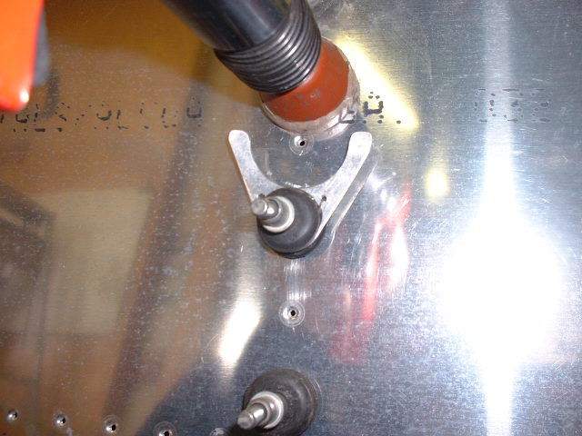
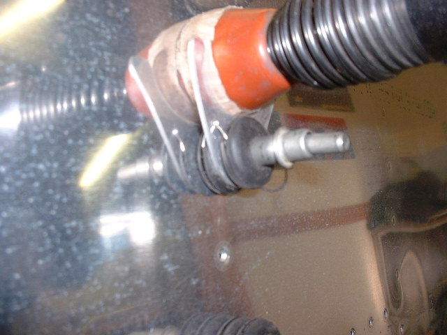
Here is today's addition to the tool box. I have used grommets on a clecoe as a rest to hold my rivet set in the right spot when I am riveting alone. The grommets are sized so that the rivet set is centered on the hole above the cleco. A friend was in this morning and suggested a mod and I include a couple of pics so you can make your own. Materials, one clecoe, two grommets, one piece of scrap .063 metal and a bit of safety wire. The grommet rests firmly against the metal and keeps the "rest" from turning. Tom Martin *end of comment*
Buy a pneumatic squeezer. They are worth every penny and you can sell it when you're done with it for nearly what you paid for it. I highly recommend this tool! Vince *end of comment*
Take all of your dimpling tools and rivet sets and use your scotchbrite wheel to polish all of the square edges off. This will greatly eliminate unwanted marks and scratches on your aluminum parts.
Be sure to grind one side of your dies (the female ones) nearly off so you can get the die right next to flanges and other tight spots. I have seen more than one builder try to use the full size (as purchased, unground) dies too close to a flange and the die will bite the inside radius of the flange and ruin the part. *end of comment*
Don't get in a big hurry to rivet. In other words, don't rivet anything together until you have to. You'll drill out a lot less rivets this way because if you rivet too soon you'll often realize that you forgot some item that is now much, much harder to install now that everything is riveted tight! Vince Frazier *end of comment*
Fixing dents: If the skin is simply recessed a bit from normal riveting, don't be afraid to use a block of wood (or long rivet set) and a hammer to tap it out from the back side. You can really improve the looks of your bird with this simple technique.
If you've made a real live dent and it's just in the skin, but not over a flange, you can dolly it out a bit with your bucking bar and flush rivet set. If the dent is still offensive, drill a hole right in the middle of it where the dent is worst, take a scrap of .063 and match drill and countersink it, rivet it behind the dent. Use 2 rivets if necessary. The 063 will hold the skin flat and the dimpling operation will soak up some of the dent. Obviously this fix is not for the faint of heart, but it works.
If somebody questions you later about the unusual placement of those rivets... tell them that those rivets hold the " altitude compensation solenoid for your beta version flight data transducing oscillator" or just beat them senseless. ;-)
A neat trick to help make really flat rivet lines is to put a thin layer of JBWeld between your skins, cleco every hole, and drive the rivets after it sets. The JBWeld (3M makes a similar product) acts as a perfect shim to suck up any misfitting between the sheets. I can sense lots of flames coming.... no, I'm not advocating using JBWeld to make up for stupid building mistakes, only as a device to make properly fitting parts fit better.
Filler or Bondo... No thanks. I worked hard to put those dents there and there they will stay! Vince Frazier *end of comment*
As far as skinning goes, I back riveted the whole rear fuselage with a few exceptions. Mark will attest that it turned out beautifully. And when you are the shooter, anyone can hold a big bar on the outside of the skin. My wife, sons, and friends did this while I cramped up in the tail. When shooting skin onto bulkheads make sure the skin is not being sucked in, add shims where ever necessary to make the skin fit perfectly. Even when the skin fits perfectly it can still start getting a gap between the inside bulkhead and skin When this happens...........try this trick: When two skins start gapping when shooting, get a piece of sheet lead like roofers use (the sheet I think is about 1/16 to 3/32 thick) and put it right on top of the shop head and shoot easy with bucking bar in place. If you can't hold it with your fingers use some carpet tape and tape it to the bar and buck the offending rivet. The lead will draw up the gap in the aluminum, and not mar the skins because it is softer, and generally buck the rivet also. ( An appropriately sized rubber O-ring between the bucking bar and work piece will also work. Vince ) Practice in a vise with some scraps first. Tom Martin *end of comment*
A Technique for Trimming Skins
Several possibilities exist for trimming the edges of skins after marking the cut line:
1) Use a large hand shears and carefully follow the cut line in
two or more passes.
Problems:
a) Tends to make a wavy cut unless you are really good at following the line.
b) May roll the edge in the process depending on the quality of the shears.
c) May make ripples on the edges.
d) Hard on the hands to cut .032 material.
2) Take them to a sheet metal shop and have them sheared on a
big shear.
Problems:
a) May be inconvenient in time and travel.
b) Probably will cost you a bit, unless you have a friend in that business.
3) Buy an air operated hand shears and do it yourself avoiding
the above.
a) Makes a straight cut if you use a guide.
b) No ripples or rolled edges.
c) Saves your hands.
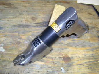
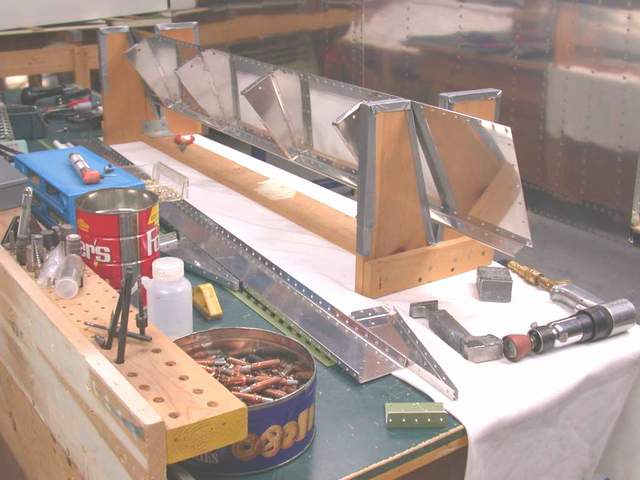
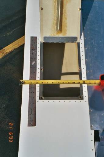
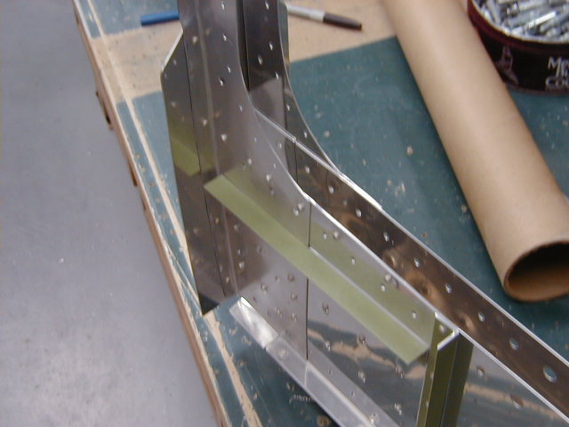
I bought a "Pistol grip air shears" made by Central Pneumatic from Harbor Freight (PN 36567-2VGA) for $45.99 plus shipping. (www.harborfreight.com). These shears cut an approximately 7/32" wide slot between their two "feet." Before starting I took the jaws of the tool off and filed the sharp outer edges of the feet round to prevent as many scratches as possible. I also practiced cutting some scrap .032 aluminum to get used to the behavior of the tool. A swivel on the air hose connection would be helpful too.
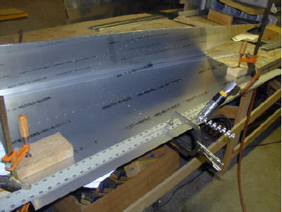
The second photo shows the shears in action being guided by a 6’ aluminum ruler clamped 7/32" inside the cut line to allow for the width of the right-hand foot. Notice that the ruler is clamped on both ends with vise grips as well as in the middle so it can’t move sideways as I cut. The skin is also clamped to the table so it won’t move. At this point I’ve already drilled the skin and the protective coating is still in place. In this photo I’m ready to remove the middle clamp and continue on with the second half of the cut. It’s also important to work from the inside of the skin so any scratches are on the inside.
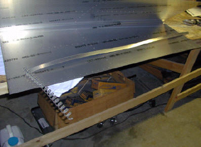
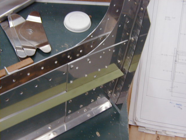
The last photo shows the waste aluminum I’ve trimmed off in a single pass with the shears. If you’re careful and patient, the resulting edge will be straighter than you can easily do with hand shears, and the edge will be free of ripples and slivers. You’ll find that the edge will be very crisp due to the thousands of cutting strokes the shears use to make the cut! All that remains is to finish the edge with your file and sandpaper.
You can also use these shears to trim the outer ends of the skins for the elevator counter balances! Mark Yelich F1 #86 *end of comment*
Tail feathers:
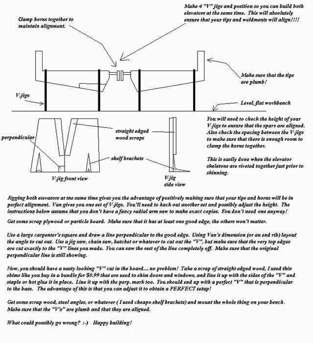
The first thumbnail above shows a sketch of how I jigged both my elevators together to help eliminate any tendency for the tips or control horns to be misaligned. If you can't view this clearly in your browser when expanded, copy it to your computer and view it with one of the JPEG photo editors. Or click on FILE then PRINT PREVIEW in Microsoft Internet Explorer and view it at 100%. Vince Frazier *end of comment*
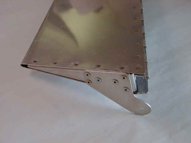
The photos above show the ribs that I made to eliminate the pesky bends that are normally used on the ends of the trim tab. Vince Frazier *end of comment*
The tail is built from Van's plans with only minor deviations. The leading edge of the vertical stabilizer is trimmed on the bottom edge to clear the turtledeck, which is slightly taller on the HRII than the RV-4. Easy enough. Vince Frazier *end of comment*
The control surface leading edges are your choice. You can roll them and leave them as Harmon shows, or close them up like Van recommends. I did mine like the RV-4 plans show. Vince Frazier *end of comment*
Slowest level speed with full up trim on 42 HR solo is 105 mph with a passenger speed is around the stall. Trim size to RV-4 specs. John Harmon *end of comment*
I had put a bigger tab on my ship, to get the trim speed at min loading to 85MPH. Well, I came close, as I get 90 or so. The flip side of this coin is that the trim is REAL sensitive at cruise! Not so good, but I have gotten used to it. If you will use electric trim, and one of Matt Dralle's speed control units, you can have the bigger tab for better low speed control, without the sensitivity I have with my manual unit. Mark Frederick *end of comment*
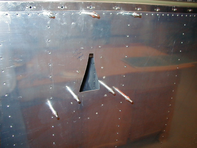
Q: Can someone tell me if the holes in the 406 and 407 for the elevator control tube are okay if sized according to the RV4 plans? I was looking through my photo archives and it appeared that it needed to be enlarged on a friends RV4. He made his sort of a rounded triangle that looked about 3" across at the 406. Am I missing something?
A: Yes, the holes have to be enlarged as you noticed. The hole dimension that Van gives is just a place to start. On both of my rockets I have had to raise the rear stick 1/8" higher to get clearance between the push tube and the rear spar pickups at the number six bulkhead. Each plane will be slightly different so you may not have to do this.
Q: What are the callouts for the degree of travel of the emp control surfaces?A: Set the rudder for 30 deg right AND left; set the elevs for 30 up & 20-24 down. The trim tab will move about 40 deg total -- skew this so you get more 'nose up': 25 deg down; 15 deg up. Mark
Here's a later answer to the same question....
Q: I can get my 30 degrees up on the elevator with no sweat but 25 degrees down is about it with out major hacking. Do I really need 30 down? I also need the travel limits for the trim tab.
A:25 down will be fine -- you will need to trim the lower flange at the center of the
spar for the elev horns to clear...
40 deg travel on the tab: 15 UP (nose down) and 30 DOWN (nose up). That will certainly
confuse any non-pilots! You may need to enlarge the slot for the actuator rod too.
Mark
Q: F-1 Rudder counterbalance, does it get a lead weight?
A: Yep -- the rudder gets a weight too, to change it's harmonic frequency (flutter frequency). You can buy a weight form the fine folks at Brand V, or pour your own. Use 850g (rudder) or so if you make your own. The elevs balance as you would expect. If you pour your own, be sure to use substantial fasteners to hold the weights in place (double nutted washers etc) -- it's very interesting when a weight comes loose and jams the controls! If you buy me enough beer, I'll tell you about it. Of course, you have to drink just as much, or you won't believe me! Mark
Rudder:
The bolts that connect the rudder cables to the rudder pedal have been known to come loose, often with disastrous results. The cotter pin that holds the nut in place can be broken by repeated contact with the pilot's shoe. Van has a "service bulletin" regarding this problem.
Be sure to inspect this area if you're already flying. The fix is to use an MS17825-# self locking castle nut in place of the normal castle nut. The nyloc feature of the MS17825 gives you extra insurance that this critical nut won't come off. Some builders even put a dab of JB Weld over the remaining exposed bolt threads. Locktite and safety wire are other possible cures. Whatever you chose to do, just make sure that those nuts NEVER come off accidentally. *end of comment*
Wings:
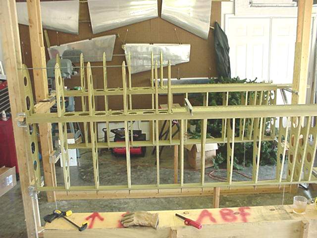
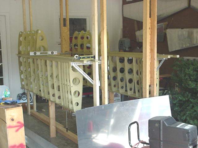
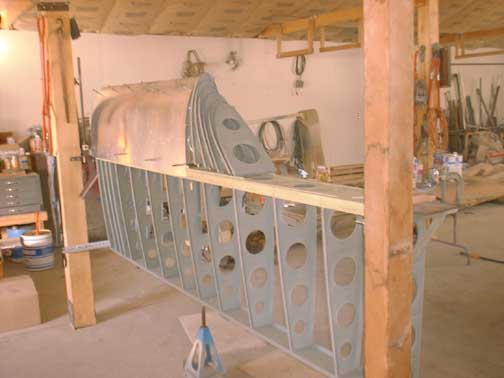
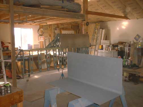
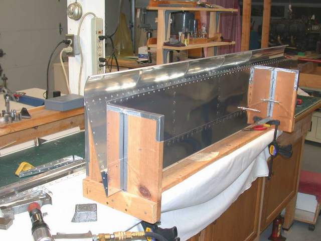
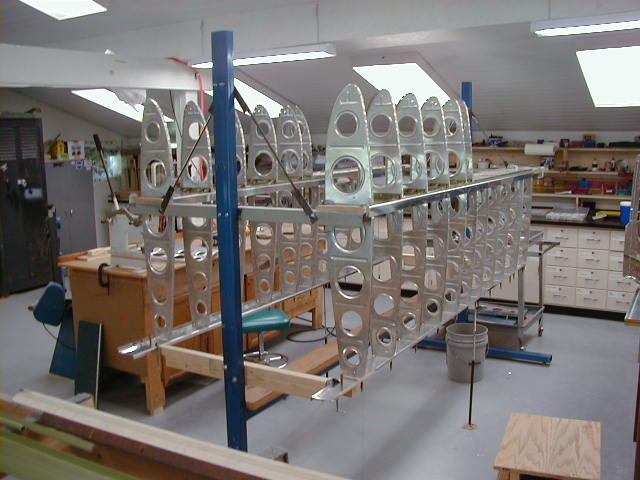
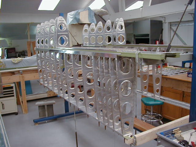
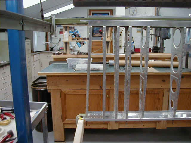
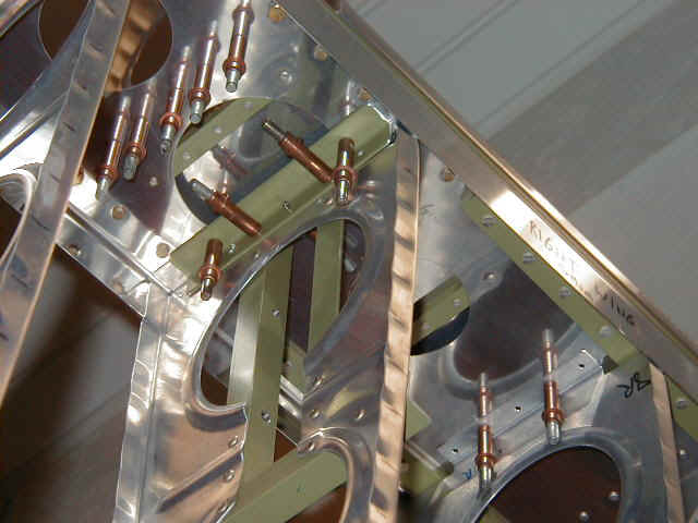
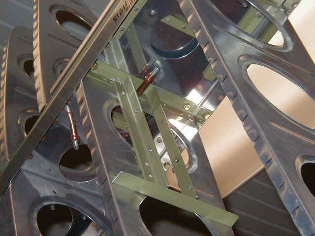
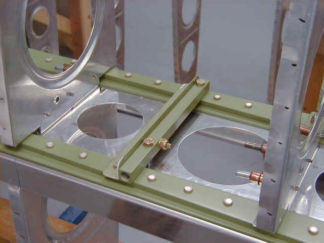
Photo #1 and #2 show the wing skeleton. One item not shown is the wiring conduit for the strobe and landing light wires, which wasn't installed yet. I used a 5/8" OD piece of hot/cold plastic pipe from Lowe's. Be sure to ask for their "aircraft grade" water pipe....(wink, wink). The pipe is heavier than some other methods, but the price is right ($1.96) and it can be removed easily if not used. You can glue a pipe connector on each end of the installed pipe to hold it in place or use safety wire or drill a hole through the pipe for a cotter pin.
Photo #3 shows the root rib which must be bent slightly near the main spar to fit well. Use your fluting pliers to make a bigger flute right where the joggle on the flange is near the main spar end and then bend the rib as needed.
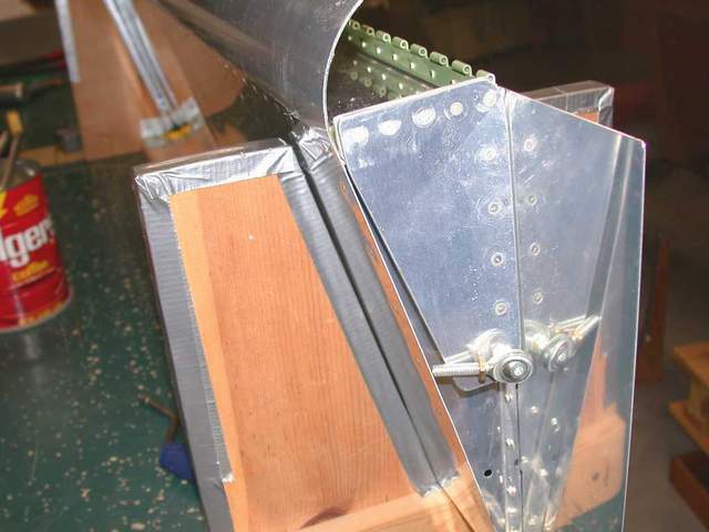
Photo #4 and #5 show how I constructed the aileron bellcrank rib. Mark suggests turning the rib around so you don't have to add a small splice to the stiffener near the spar like I did. I suppose either way is fine. If you look closely you can see that I drilled two holes for the aileron bellcrank. That's what happens when you drill the hole in the angle and then realize that you riveted in on backwards. The one closest to the spar is now officially a lightening hole!
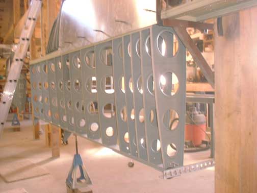
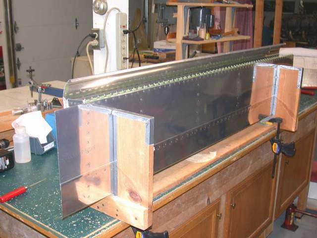
Photo #6, #7, and #8 show the F404 bulkhead. Harmon's F-404 bulkhead parts were fine, but I didn't want to drill all those stinking bolt holes and try to keep everything aligned. What I and others have done is to splice on a couple pieces of aluminum on each side of Van's F404C&D bulkheads. I simply placed Van's parts on top of Harmon's parts and cut the overhanging portion off of the Harmon parts. Then using the remaining material from Harmon's parts, I made splice plates to hold it all together. Spacers were required behind the 6061 stiffener angles to keep everything smooth. Some head scratching required, but it seemed easier than drilling 80+ holes in John's pieces. This area gets gobs of support from the wing spar, floorboards, skins, etc so I wasn't too concerned about putting a splice in here. I used John's F-4A&B uprights since Van's parts had holes that didn't line up where I wanted them.
Photo #9 shows the splice I made to the tank support. Probably not necessary, but I like it.
Photo #10 shows the tiedown bracket installed on the front of the spar. Mark suggested and I agreed that big holes in the spar flange weren't a great idea. Once again, probably not necessary, but I like it better that way. Vince Frazier *end of comment*
A builder asked me why I hadn't riveted all the wing substructure together yet. I have my main spar completely riveted. My rear spar has the root flange strips and doubler plate riveted on. Skins are all drilled and the tanks are finished. But none of the ribs are permanently riveted in yet! Why???
There are several reasons that none of the ribs are permanently riveted yet. All are bolted in position though, I just have put off setting the rivets in case I need to pull one rib out for some reason. I typically put off riveting anything as long as possible. Doing so has eliminated drilling out a bunch of rivets like I did the first time around on my RV-4. I also get to show off my extensive cleco collection....LOL After you get everything drilled, deburred, dimpled, etc... basically to completion, look at it awhile to make sure you didn't forget something, then rivet it together after you're sure everything is done. If you realize that you forgot something, well just pull a few clecoes and install the whatchamakallit with ease.
Similarly, the aileron hinges and doublers on the rear spar should wait until you've got the ailerons built so you don't rivet the hinges in the wrong spot. You'll be sorry if you blindly follow the plans and drill them to the spar too early!!! You'll probably want to mount the aileron, then build the flaps AFTER mounting the aileron so you can match the trailing edge, then after everything else is done rivet the bottom skins on.
A few other things I did differently on my wings... I put a wingwalk doubler under the skin on the right wing too. Just in case I want to stand on that side to clean the canopy or whatever. Maybe I'll switch to a slider and want to get in or out on that side. This was something I'd wished I'd done on my RV-4.
I shifted all the skins outboard by 1/8" so it would be easier to mount the wingtips later. The only place that this had any impact was on the inboard leading edge rib (just outboard of the tank). The doubler on that rib easily accommodates the shift outboard so there was no problem. Since you are shortening the RV-4 wing by 7 1/2", there is plenty of skin to work with.
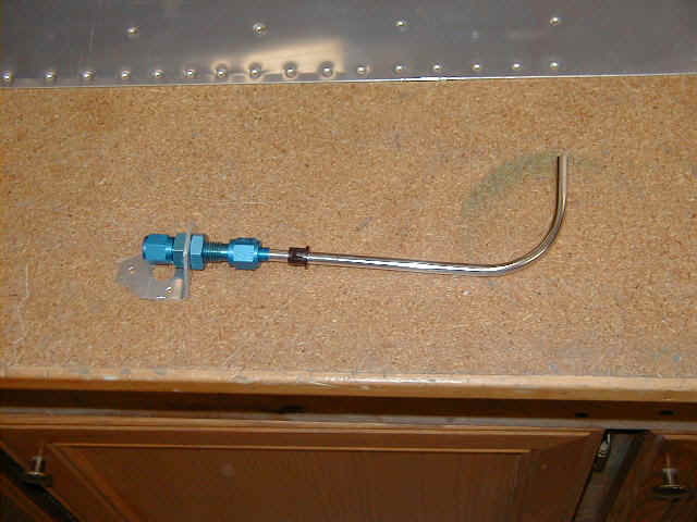
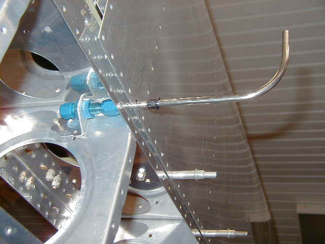

I made an angle piece to mount the pitot tube inside the wing. That way only the tube sticks out of the wing and all the big, ugly fittings are inside. The only other thing exposed is the snap bushing that the pitot tube goes through. You could use a rubber grommet if you don't have an extra snap bushing. Also shown is the LRI that I purchased from Al Mojsizik.
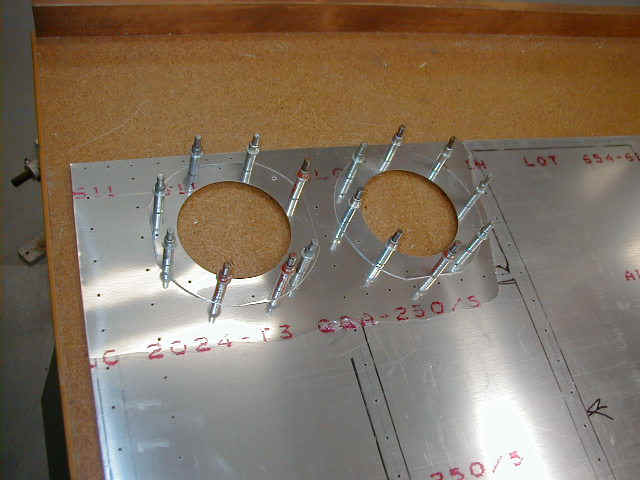
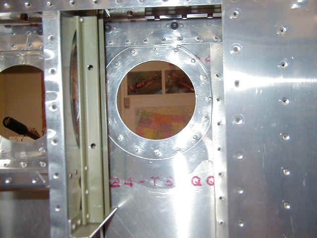
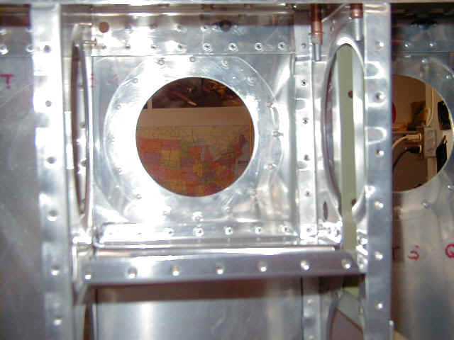
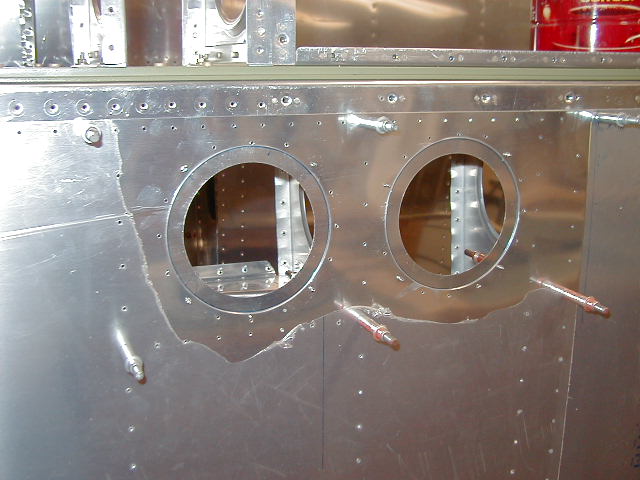
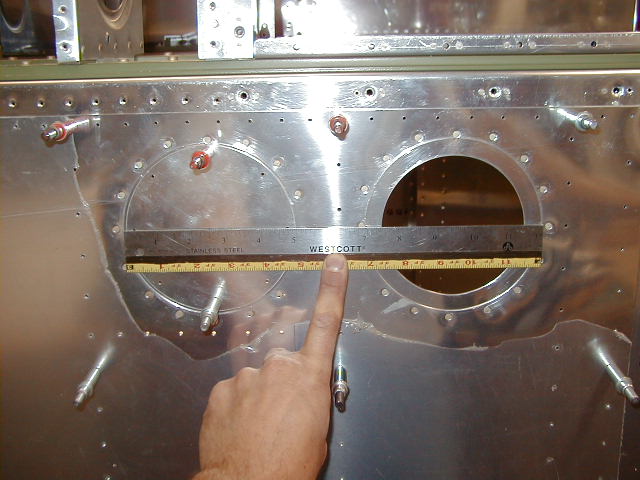

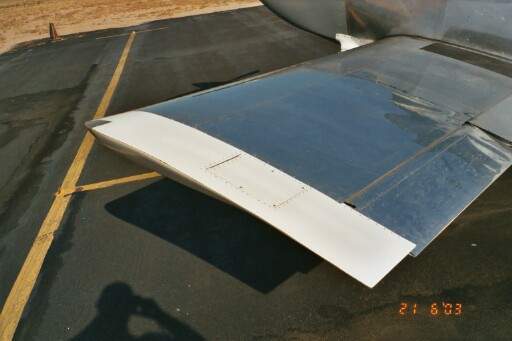
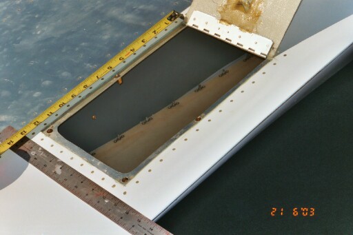
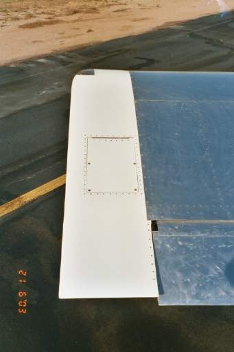
Here's a couple shots of the round aileron bellcrank access panels I made. I made the thing just a bit too big and had a minor edge distance problem with the doubler rings near the spar flanges. You can see the rivet at the 12 o'clock position is right on the edge. No big deal. I cut the hole in the skin to be 5" and the center of the doubler ring was 4". My hand fits inside easily and I am pleased with them, even if they're not quite perfect.... Oh well, no trophy for me! (Like I care.)
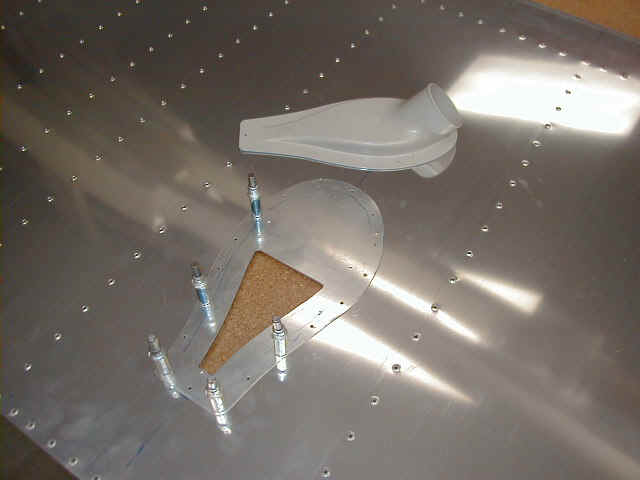
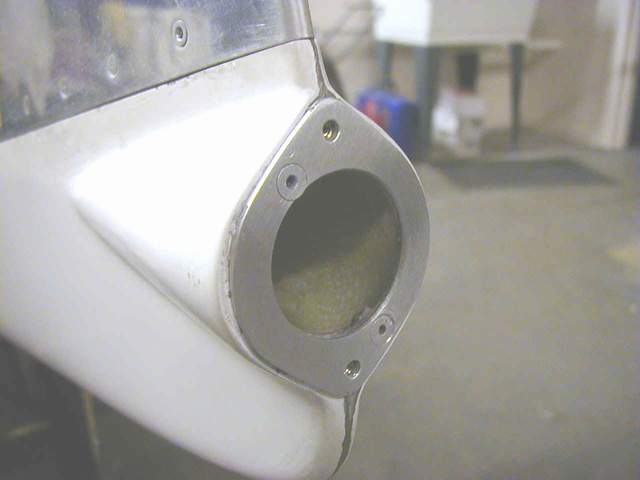
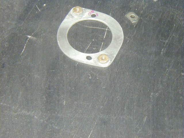
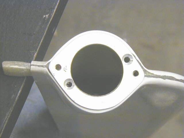
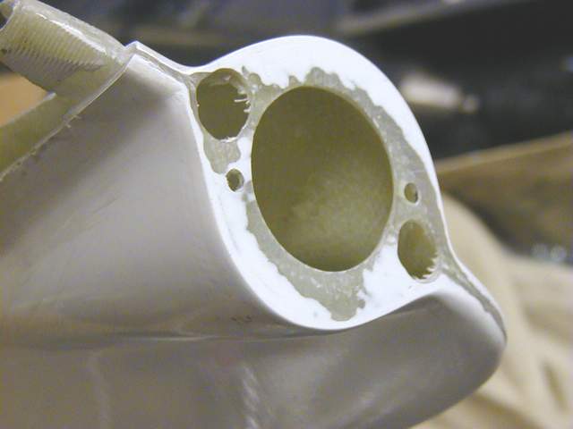
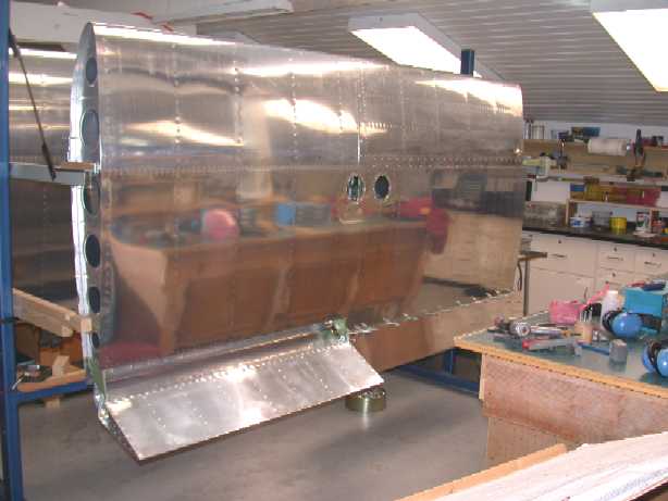
Here's the air scoop for the rear seat ventilation. I ProSealed the scoop to the doubler. The doubler gets riveted to the bay just outboard of the wingwalk area and 3" behind the spar. Make sure you put it in the BOTTOM of the wing. Laying out these #$%^& pieces reminds me of a saying that I am fond of.... "PREPUNCHED IS FOR SISSIES!" LOL. *end of comment*
Q: Anyone have a description of the fresh air NACA intakes in the underside of the wing?
A: Hi Russ: I put the inlet in the first bay outside of the wingwalk ribs, with the front edge of the cutout 3" from the skin butt-joint. The 2" hose routes thru the rib lightening holes (third one from the front) and thru a hole in the lower side of the fuselage. Careful routing of the hose will allow this to work with footwells, too.
Q: As for the ones in the wing bottom skin, any chance of exhaust coming in there?
A: No -- it's placed far outside the exhaust stream. *end of comment*
I am working on the fresh air inlets just now. Mark has cut one hole in the left wing and routed it to the left rear seat. I will cut another on the right wing far enough out (third or forth bay, I think) and route it to the forward cockpit. Should be far enough out so as not to pick up engine smells. I will also have an inside panel to finish the side walls which will act as a plenum for air distribution through the vents. Don't know where Mark gets his NACA scoops but Vans sells them as well. *end of comment*
I left the first THREE ribs temporarily bolted in place. Then when you're riveting the skins on you can pull them out for easier access to those rivets. The only problem this causes is that a couple of the rivets holding the flap brace are less accessible, but this is more than compensated for by the easy rib riveting.
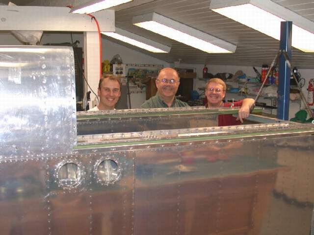
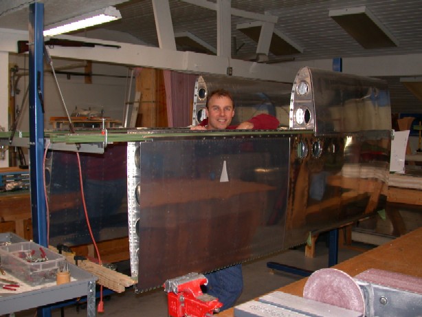
Above: Master Builders..... Bow before our stupendousness, knave! :-) Left to right: Vince Frazier, builder/owner/bucker; Steve Steckler, RV-8 builder and chief rivet sticker inner; and John Crabtree, RV-6 builder and master (rivet) gunnery sergeant. What a team. You can't believe how fast you can close a set of wings with 3 experienced guys. Three guys work well, one to gun, one to buck, and one to put rivets in the holes. The bucker really appreciates the extra speed so he doesn't have to hold his arm at odd angles too long.
I have my wings completed now. Vince Frazier *end of comment*
Above: Mark Kellum's wings.
Above: Mike Horton's wings.
The Rocket wings differ from the RV-4 in that they are about 7 1/2" shorter on each side. Vince Frazier *end of comment*
Q: Is it still considered good practice to make a small gap between the tank skin and the LE skin? If so, how much? I'd guess something like 1/64 - 1/32.
A: It is important to leave a gap. Not only between the tank and the leading edge skin but between the tank and the main wing skin. The wing, as rigid as it is, does flex. I have noticed some chaffing of my paint between the main skin and the tank skin as I had them butted right up to each other. Allow at least 1/32 of an inch. If the gap is uniform it will look right. This also applies to other areas in the aircraft, for example the cowlings and canopy joints. *end of comment* ( I used 0.020" between the leading edge and main skins... coincidentally that is the thickness of the steel ruler that was in my hand at the time. Vince Frazier)
When fitting the tips to the wings it is difficult to hold and position them at the right location while at the same time holding them snug up to the leading edge. While struggling with this awkward shaped thing I happened to glance over and see one of my truck tie down straps. The kind with the ratchet. Place the strap around the leading edge of the wing, inboard a couple of inches and then the back of it looped around the trailing edge of the wing tip and tighten it up! An added advantage is that it will stay by itself and you can raise and lower the trailing edge until it lines up with the flaps and ailerons. Tom Martin *end of comment*
I just cut my one piece top skins to size and found a way to make the nearly10 foot cut easily. I clamped the sheet to a piece of 12 foot particleboard and cut it with a piloted, straight bit in a router using the edge of the board as a guide. Way easy, very straight, and fast. The bit I used was a 1/2" straight bit for Formica. Smaller would make even less chips. I highly recommend this as a way to make long cuts. *end of comment*
Q: I'm about to drill my one piece top skins and noticed the spacing on the .025 outboard is 1" down the main ribs. If using a one piece .032 skin, can the spacing safely be 1.25" as on all the other skins? Perhaps this is just a typo on the Vans drawing.
A: 7/8 "front spar, 1" rear spar and 1 1/4" on the ribs. John Harmon
Spars:
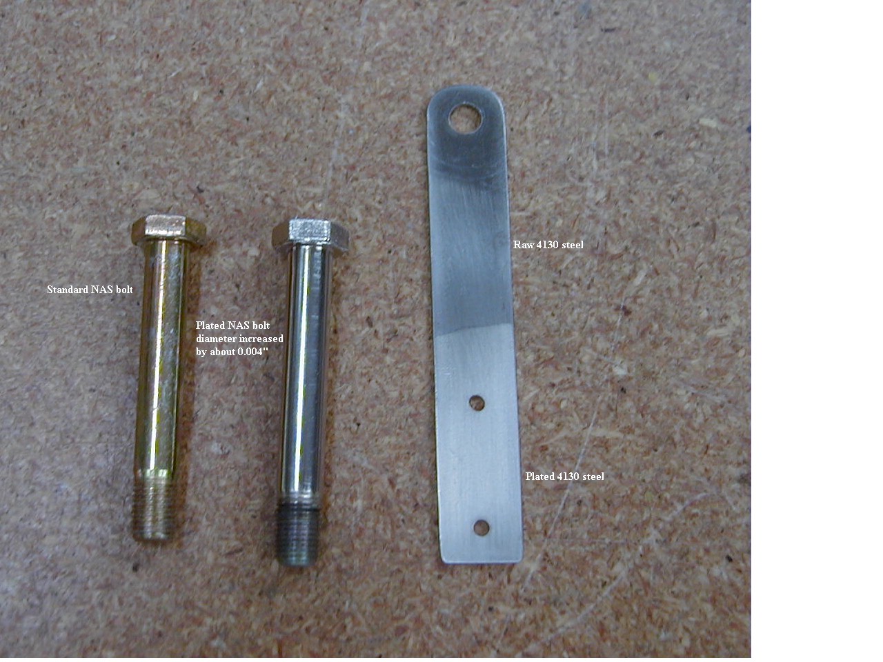
I was cleaning the Stits epoxy primer paint out of my spar bolt holes using an appropriately sized reamer (0.373" for the 3/8" holes, and so on). It was going fine, until I inadvertantly picked up a stepped reamer that was 0.377" on the top part of the shank. Sure enough, I reamed one bolt hole out to 0.377" and the NAS bolt was a sloppy fit. I hate when that happens!
I realize that one bolt probably wouldn't make any difference but I wanted to fix it anyway. I thought about reaming up to the next size (10mm, IIRC), but wasn't wild about that option. I could always do that later, and besides, who wants one odd bolt in their spar?
Here's what worked for me: I contacted Caswell Plating (www.caswellplating.com) and bought an 8oz. bottle of their CopyChrome nickel plating solution. Following their directions, I plated the bolt up to 0.377" then baked it at 400° F for 4 hours to take care of any hydrogen embrittlement. It worked great.
I also plated some 4130 scraps and was pleased with their appearance. The plating looked like it should be pretty durable. I even soaked a 4130 piece in saltwater overnight and saw no effect. It's not quite chrome, but it looks pretty good. Vince Frazier *end of comment*
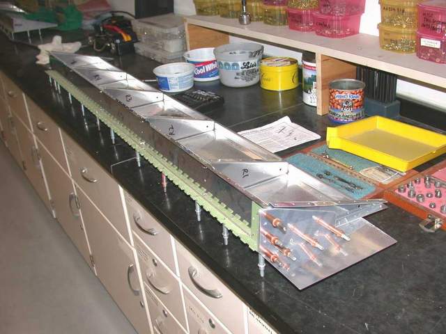
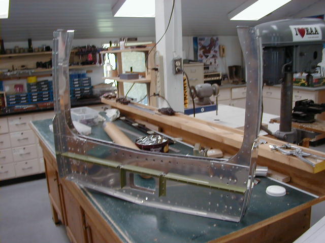
Tanks:
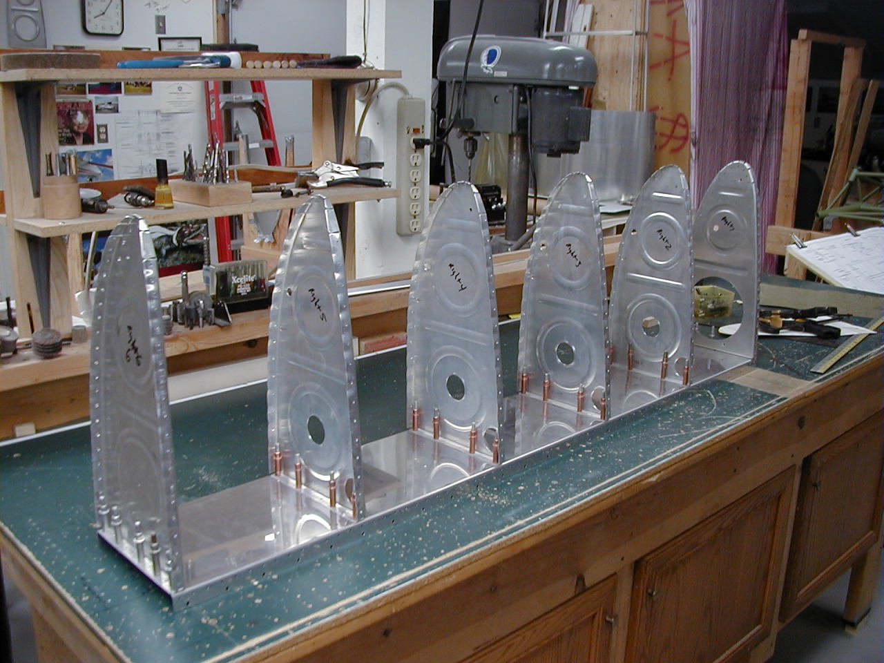
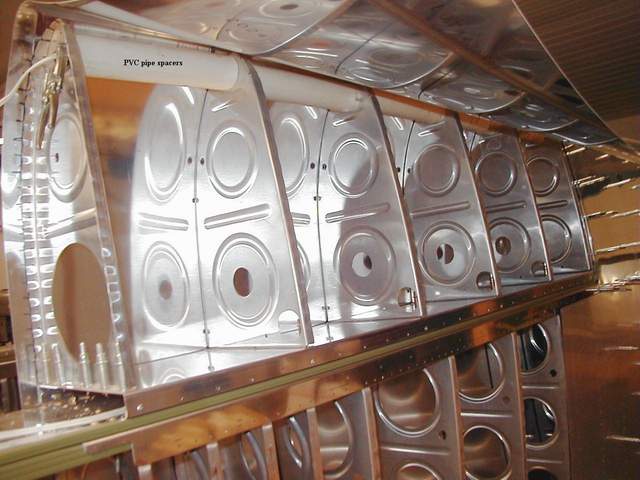

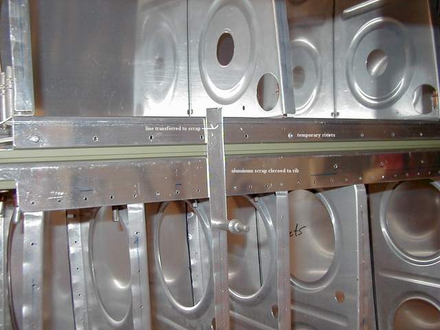
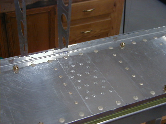
Photo #2 shows the tank assembly ready to be temporarily riveted to the spar tank flange. I had used spacer blocks previously on my RV-4 to set the tank assembly position on the spar. Spacers will work, but I think it leaves the assembly much too wobbly for strapping the skin down prior to drilling the ribs. I aligned the tank assembly on the spar by using a thread stretched through all (from wingtip to root) of the tooling holes in the wing ribs and tank ribs. When I was satisfied that the alignment was perfect, I drilled a hole in the spar tank flange and tank baffle at each rib intersection and temporarily pop riveted the assembly to the spar flange.
Photo #3 shows the tank assembly in place. It is temporarily riveted to the spar tank flange using all aluminum cherry rivets. Use any rivet you like as long as they are easily drilled out, i.e. make sure they're all aluminum. You can see several sections of wide (2 1/2" or so) PVC pipe that stabilize the forward portion of the ribs. The PVC is held in place with a piece of wire that runs through the tooling holes. Everything is rock solid. The top skin is already positioned and partially drilled when this photo was taken.
Photo #4 shows how I back drilled the tank screw holes. The tank screw holes under (behind) the spar were backdrilled in a similar fashion... DON'T HIT THE SPAR BARS! Next, the top of the tank skin is ready to be drilled and clecoed to the ribs and tank baffle. (See the note about the line finder in the following paragraph for Photo #5) The next step will be to pull the bottom skin into position and drill the rib rivet holes.
Photo #5 shows one of the little aluminum scraps that are used as a line finder. You'll need them. The rivets that attach the tank skin to the tank baffle are in a tight spot... no room for error. Simply mark the rivet line on the tank baffle. Next cleco an aluminum scrap so that part of the scrap overlaps the rivet line. Make a corresponding mark on the scrap where the rivet line will be. Then swing the scrap out of the way and position the skin and drill the rib rivet holes from the leading edge down, pushing the slack out of the skin as you go. Next, swing the scrap back up and transfer the marks onto the skin. Now you're ready to drill the tank baffle rivet line without fear of missing the mark!
When you get all the drilling and deburring done, it's time to scuff everything up so the ProSeal will stick. Don't be bashful. Rough it up. I used a 4" abrasive impregnated nylon wheel from Lowes. It looks like a regular wire wheel but the bristles contain no metal. Van's recommends using a stainless steel bristle brush. I'm sure that would be OK, but the chemist in me didn't like the idea of scrubbing the dissimilar metals due to my galvanic corrosion concerns. Also, the stainless steel brush made my arm tired, whilst the nylon wheel was much faster, did a great job, and didn't wear out my arm.
Dimple or countersink now as shown on the plans. Then degrease everything to remove fingerprints, air drill oils, ink marks, etc. There's a million ways to do this. I used wax and grease remover from the auto paint store and then followed up with an acetone wipe. Just make sure everything is scrupulously clean and then don't touch it. The part about not touching it is tough.... I think I used two full rolls of paper towels to re-wipe stuff I handled. Use the all white paper towels that come in half sheets. Don't use the ones that have flowery kitchen scenes on them or your burly airplane buddies will make fun of you. Also don't use the expensive thicker, quicker picker upper because your wife will kick you for being wasteful, and since you've got a $6000 propeller to buy you shouldn't be ticking her off.
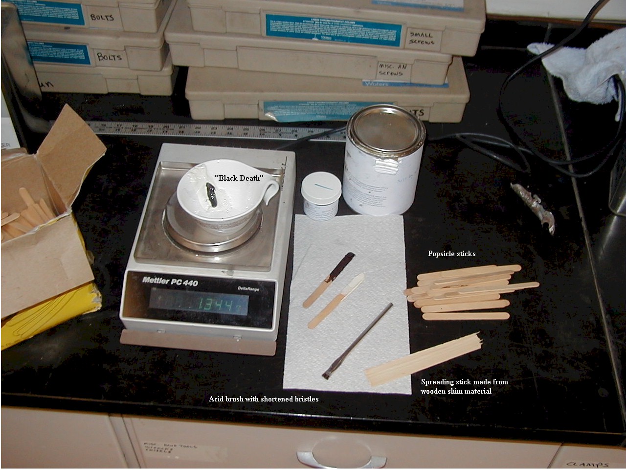
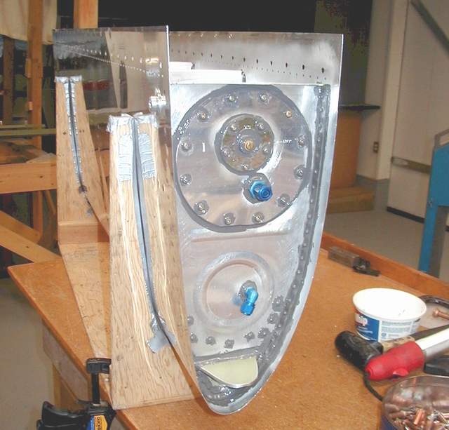
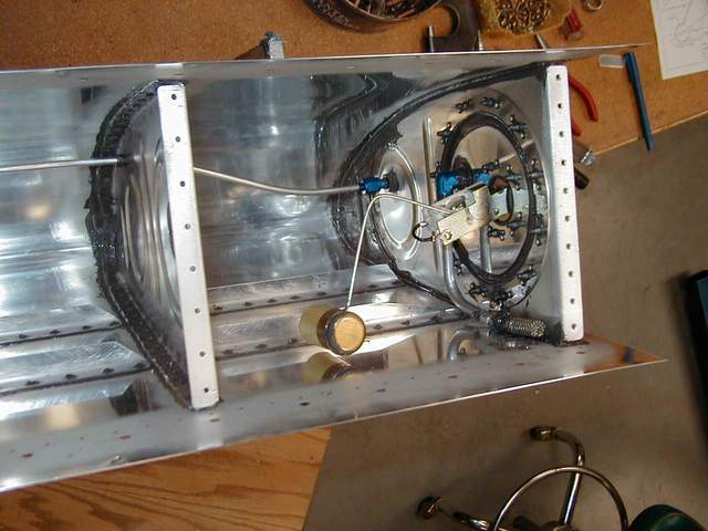
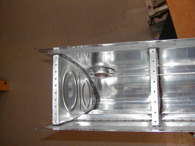
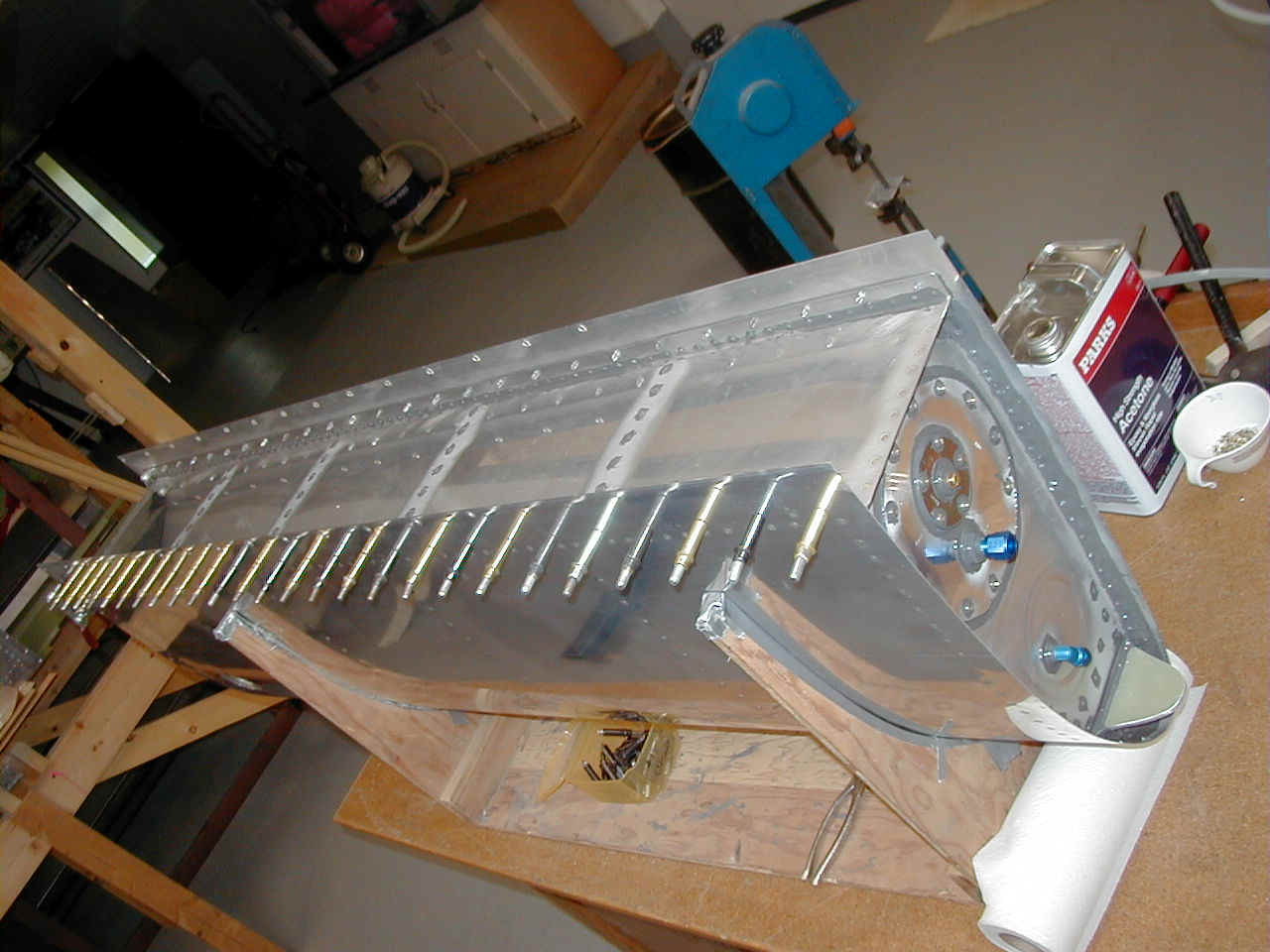
Photo #6 shows some of the stuff you'll need to mix and spread the ProSeal. Pretty self explanatory. It mixes 10:1 by weight so the math is easy regardless of how much you make. I mixed batches from 10 to 100 grams. 10 grams was enough to put on the access plate and 40 grams was enough to put in a couple of ribs. The rear baffle took 100 grams. A single can of ProSeal is more than enough to do both Rocket tanks if you don't waste it. If you trowel it on sloppily though you will run out. Plus that ProSeal goop is HEAVY so just take your time and use it moderately.
Photo #7,8, and 9 show the tank nearly complete! Hoo ha! If you don't already have a simple jig like is shown in photo #7, build one immediately using whatever scrap plywood you have around. It's gonna get all messy anyway!
Cleco all the ribs in position prior to putting ProSeal on anything. Remember how many straps you used and how difficult it was to get everything together while drilling the rivet holes? Use a deadblow hammer or your palm to tap the ribs into place because they won't want to go back in place! An icepick (Get one, but don't take the wife's icepick from the kitchen. It's important not to tick her off!) is VERY useful for all rivet hole alignment problems. Use it to GENTLY manipulate the holes into alignment.
Next remove one rib at a time, starting in the middle, butter the rib and the skin with thoroughly mixed ProSeal. Use the tip of your wooden trowel (see photo #1) to force the ProSeal down into each rivet dimple. Otherwise there will be an air bubble and potential dry spot (LEAK!). Re-install the rib. Stick in the rivets and press them in completely using the tip of the icepick. Proseal should be everywhere by now, including on the dog, your beer can, on your face, and on the outside of the tank around each rivet.... wipe off the excess for easier riveting using a solvent dampened, but not dripping, rag.
Important: If you're new to riveting the fuel tanks are NOT the place to learn. There are two standards for riveting... the "almost anything goes" tank standard and the "perfect" standard for everywhere else. Tank rivets are a major pain to drive consistently. The ProSeal lubricates them and hides them from visual observation so the $%^&ed things clinch fairly frequently. And since you have trouble seeing them it's difficult to tell when to stop. Plus they stick out externally! (Maybe I should've bought tank dies!) I didn't drill out any rivets on this set of tanks. The shavings make a real mess and if you enlarge the hole any it will be even harder to drive the next rivet. So, just drive 'em and take whatever you get. Hopefully, all of your riveting boo-boos will be on the inside of the tanks and the outsides will look good. (There are undoubtedly builders out there who will argue with this! Pay them no heed. They're too busy winning trophies anyway.)
OK, you've got all the ribs riveted in and have ignored the 10% of the rivets that clinched and made you curse and swear. What next? Start cleaning off the smudges and smears with solvent. Make sure to get everything cleaned off of the outside because within 24 hours it will become quite difficult. Then take the short bristled acid brush (see photo #6) and work the ProSeal around each rivet bucktail. Next, use the brush to make a nice fillet next to the joints. Clean everything again. Check for pinholes and missed spots.
You should be just about ready to install all the access plates, floats, fittings, and vent lines. Nothing special here. You'll need some washers to shim up the AN fittings so they're not loose. You'll also want to add some sort of anti-rotation tab to the fuel pickup line so it can NEVER get out of position. The anti-rotation tab isn't shown on the plans but has been discussed in the RVator, IIRC. It's just a tab riveted to the access plate to keep the pickup tube in place.
After all the inside stuff is cleaned up and double checked, it's time to close 'er up. The rear baffle (I wonder why it's called a baffle instead of something more appropriate like rear wall or backplate?) is pretty easy to install, just time consuming. I spent several hours on each side and used about 100 grams of sticky, black goo per baffle. You can use a bunch of clamps to squeeze out the excess sealant, like Van recommends, or you can do as is shown in photo #10 and use clecoes through the screw holes to do the same thing. I happened to have enough 3/16" and #22 clecoes to fill all the holes. You can use smaller clecoes if you put an appropriately sized washer behind the skin for the cleco to bite onto. Whatever you use just make sure you squeeze out all the excess ProSeal so the tank will fit properly. Also you need to make sure that you didn't leave any sealant globs where they will interfere when installing the tank on the wing. Check one last time to make sure everything is cleaned off!
Vince Frazier *end of comment*
Craig Cook sent the following tips for those who are building the optional 58 gallon fuel tanks.
I found that the W-408 undersize leading edge rib lands right over a large lightening hole in the main spar web. Here is my solution: Make a 3/4" x 3/4" x .063" angle for the aft side and a 0.040" spacer to fill area between the rib and the angle in the lightening hole. After final assembly of the 4 leading edge ribs onto the main spar, pop rivet through from the aft side forward. 4 rivets will fit into the lightening hole area and go through the flange of the front rib. There is no main rib behind this area.
The last spacer bar (3/8" x 1/2") can interfere with the #11 main rib pop rivets if it's more than 3/8" inboard from the end of the tank flange. I made the mistake of moving mine quite a bit inboard to avoid a large overlap with the big lightening hole. This allowed for 4 pop rivets through the bar, but when I tried to install the main rib angle, those pop rivets were going to hit the spacer bar. My solution was to move the 3/4" x 3/4" main rib angle inboard about 3/16" and mill windows into the angles to clear the lock nuts. Craig Cook.
Leak testing: Add 21 gallons of gasoline to each tank. There won't be any leaks because you took the utmost care to scuff and clean all mating surfaces before carefully applying the ProSeal. The best leak test you can do... take your time and keep everything clean and orderly. Well, I suppose that there are other ways. Perhaps the simplest is to put an inflated balloon on one of the fittings and see if it leaks down overnight. Many leaks occur in the gas cap, so tape over it before starting your leak test. Vince Frazier *end of comment* Leak repair: One builder's procedure to fix a leaking tank rivet:
1. Put a large o-ring around the offending rivet to form a dam.
2. Fill o-ring dam with MEK (methyl ethyl ketone) while putting tank under
Sounds potentially disastrous unless you're very careful with that vacuum!
I might consider asking someone who works in a laboratory to get a glass syringe and a Swinnex filter unit, the kind with a replaceable filter. Use these in conjunction with the O-ring procedure above to eliminate the need to use the vacuum by using pressure provided by the syringe instead. In other words, blow the stuff in!
The filter unit is needed so you can adapt to the O-ring seal. Once you see one you'll understand.
Don't use a plastic syringe since they often leach silicone contaminants.... ask me how I know! I guess plastic would be OK as long as you don't fill it with the MEK.
Wear leather work gloves in case you break the glass syringe. If you're pressing hard to make the pressure and it breaks you'd be on your way to the hospital!
You might ask your local laboratory or school chemistry department for these things. Vince Frazier
*end of comment* Tube Bending: Are those of you who are having trouble bending tubing using a pattern? With a spring bender, the initial bends in a piece of tubing are relatively easy; its the subsequent bends that pose the problems. The trick is getting it right the first time. I had problems until I started using a pattern.To make a pattern, get a length of medium stiff wire and "install" it exactly where you want your tubing to go. The wire should be stiff enough to hold its position, yet flexible enough so that you can bend it with your fingers. (Vinyl coated clothes line wire or welding rod works great.) Make sure that the wire is bent such that it "rests" in the correct position (no springback). Then carefully remove the wire pattern, set it on your workbench, and bend the tubing to match the pattern. Take the bending slow, and keep checking your work by laying the wire pattern against the tube. After the tube matches the pattern, install it in the airplane. Only minor tweaking should be required to get the tube to fit perfectly. This method even worked on the long brake run between the left side of the firewall and the right wheel.
For the tank vent tube, don't use a short stub. Instead make a +/- 360 degree loop (like a split lock washer). Lengthen or shorten the ends as required to fit. Note: You will find that the vinyl coated clothesline wire also comes in very handy when you are determining the routing and length of hoses and heavy electrical wire runs in the engine compartment. I probably used 40 feet of the stuff before I was done.
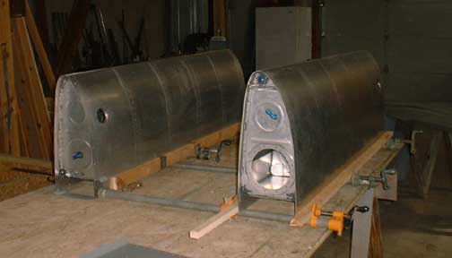
*end of comment*Flaps:
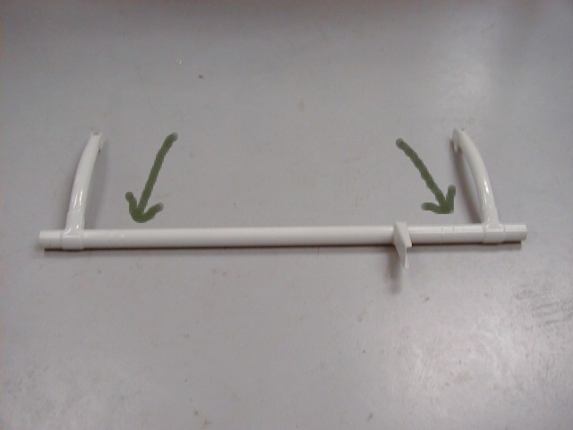
The flap tube may be cut at the arrows and a piece of 4130 tube may be welded in. This allows you to leave the flap handle bracket in place. As shown is for manual flaps. Vince Frazier *end of comment*
The RV and Rocket series seem to have a chronic problem of trailing edge mismatches and also a problem of the flaps not mating well to the belly skin.
On my RV-4 I was able to obtain a very good fit between the flaps and the belly by jigging the wings and the fuselage belly (seat ribs and 404 bulkhead area, etc.) directly to the wings prior to fuselage construction. The idea is to set the position of the 404 bulkhead so the belly area all mates together nicely with the wings and flaps. This suggestion came from Van's many years ago.
Everything was right side up for this portion of jigging. After getting the fuselage center section, rear spar carry-thru, seat ribs, F404 bulkhead and related bits drilled together, I moved the wings out of the way and proceeded to build the fuselage in the normal fashion... upside down. A little extra work but it worked for me.
When I mounted the flaps and aileron to my RV-4 wing long ago it was necessary to get a wider flap hinge to move the trailing edge aft about 1/8". After I was happy with the control surfaces I butchered the fiberglass tips to match the rest. On the Rocket I waited until the ailerons were hung before I built the flaps and avoided any wide hinges or trailing edge mismatches.
I built my Rocket flaps and found nothing particularly unusual about them. Follow the plans and it should be fine. They do get very close to the fuselage on the inboard end though. Mark recommends using flush rivets where the 1/8" plate and angle meet on the forward inboard end. Vince Frazier *end of comment*
Ailerons:
I had asked about fitting the flaps and ailerons and received the following replies.
Tom Martin's reply:
Wait until you are mounting your wings to the fuse to line up the wingtips. The process starts with rigging the ailerons where they have to go, degrees up and down. Then mount the flaps and try to get them to line up with the fuse where they look right. Now center the control stick and see where the flaps and ailerons line up. You may have to adjust the ailerons/flaps to get a nice straight line. This may mean that the flap is not in the right place in relation to the fuse. Check the underside of most RVs and you will notice that the retracted flaps do not quite line up with the fuse. It is more important that the flap and aileron work together.
When that is done place the wing tip on. There is quite a bit of adjustment in a rotational sense at this point. Take a ratcheting truck strap, place it around the trailing edge of the wing tip and the leading edge of the wing. Snug it up and move the trailing edge of the flap up and down so that it lines up with the ailerons and flaps. If it sticks out too far, well you will have to cut and glue. This is a process that has worked for me. Tom Martin *end of comment*
Eric Henson's reply:
OK, are you just starting to hang your flap & ailerons? Here's how to get them to about a human hair of being perfect. I back riveted my top skin on first, highly recommend you do this. If not you can improvise. Those wood templates are the reason most of the control surfaces don't align. They are crap, but they are useful for allowing you to work with them without fear of your control hitting the deck. (Yes, they are crap. Vince)
Take a 4' straight edge and clamp it to the outboard edge of the wing where you tips will mount. Now clamp your aileron into place as best you can and clamp the outside edge of the aileron to the ruler also. Now adjust the aileron mount on the rear spar until the ruler likes the position the aileron is at compared to the skin. Drill the aileron mount.
But Eric, I'm building an 8 you say, its all predrilled. Well, that's a bug a boo for sure. The alignment is not too great from Vans. Me and Charlie Kuss did his and the solution was to buy new undrilled aileron brackets (the little steel ones) and clamp the brackets to the aileron leading edge an pilot drill them. This got by the predrilled problem. Now do the same with the inboard. Your skin line will now flow perfectly from the top skin to the aileron top skin.
Now the flap, first cut two .125 strips 1/4 wide by two inches long. Put two holes in either end so they can be clecoed together with two clecoes. They will be perfectly flat on top of each other with the clecoes in . Now start to hang your flap, let the two pieces trap the skins where the flap meets the aileron on the top skins. This will give you the flat top alignment you want and will fix your inner position good enough. I'll stop right there because any further will not apply to the -8. Just get the aileron exactly correct and then work inboard. Let me know if any of this does not make sense. Eric *end of comment*
I forgot to take any pics of my ailerons under construction. Oops. One thing that I did to make things easier was to build a simple wooden jig to position the steel hinges exactly on the aileron spar. By using a jig you are assured that the hinge points are all exactly the same on the aileron. Not that you can't screw up elsewhere, but at least you know the hinge line is parallel to the aileron spar!
I couldn't find any one method for lining the flaps and ailerons up with the wing that I thought was optimal. I used the wooden wing templates.... two of them, belt sanded to the nth degree of identicalness.... they are still crap. I used string lines dropped from tooling holes to align everything. I used straight edges for the same purpose. I used straight pieces of bar stock clamped to the ribs. I used my calibrated eyeballs until I thought I would go mad. After double checking all of these methods, I decided that everything was close enough and just drilled the bloody aileron hinges in place and aligned the flaps similarly. Hmmmm, two laser drywall levels, one at each end of the wing, would work.... why didn't I think of that earlier. Nevertheless, they'll be fine. I'm just too picky. Vince Frazier *end of comment*
Thoughts for installing RV wings:
To do before mounting wings
1. Check fit of bolts into fuselage and wings. Clean / ream (get a new reamer!) as necessary.
2. Have “trial fit” bolts on hand (8 for new style RV spars; more for “old style” RV spars) for the largest diameter spar bolts. Leading edge of bolts should be tapered (down to about ¼” with gradual (about 1” long ) taper up to full size) and be at least long enough to protrude (untapered portion) thru both spar receivers (nuts not necessary). “Trial fit” bolts are Grade 3 hardware store bolts with threads cut off. Check these bolts for burrs and proper diameter (should be .003 to .008” less than final bolts).
3. Mark fairing screw locations on bottom of each wing, make “transfer marks” so position can be found later. Transfer mark = line extended about 6” outboard from each hole location; place mark on this line that is exactly 3” (actual dim not important as long as it is consistent and you remember it) from each intended hole center.
4. Have 4 plumb bobs and string for spanwise alignment. Skinny string is better.
5. Have measuring tape for tail to wingtip measurement. Establish measuring point in center of aft upper fuselage.
6. Use file to put slight taper on inboard fwd and aft faces of butt of each spar. Check for burrs.
7. Grease inside of each 7/16” bolt hole.
8. Check fuselage spar receiver for burrs, grease inside of receiver and each corresponding bolt hole in fuselage receiver.
9. Other fuselage prep: seat backs out; fuselage floors in (or temporary boards in their place) except provide access to rear of spar bulkhead; control sticks out (not mandatory, but nice); RV4,8: remove rear seat back (for more leg room); RV6,7,9: baggage bulkhead can stay or go depending on how much leg room you need;
10. Have kneeling pads, light, mirror, and small hammer inside fuselage.
11. Pre-make block of correct thickness called out in plans to set wing angle of attack. (~2.7”?)
12. Insure enough space exists around plane to insert wings.
13. Have padded stool or sawhorse available to set outboard tip of wing on to rest.
14. Make wooden pry block to assist sliding rear spar into fuselage carry thru.
15. Remove fuel lines and other protrusions from wing mating area of fuselage. Remove gear leg fairings and wheel pants (especially from tail wheel versions). Tape wiring and other flexible stuff so it will stay out of the way (both sides of fuselage and each wing root).
16. Wing tips, ailerons, and flaps should be off the wings. At a minimum, flaps must be off the wings, as they will definitely be in the way.
17. If not already done, cut stick to bellcrank pushtube. At minimum, install receiver and rod end in one end; leave the tube longer than plans call for. Install pushtube assembly in each wing (slide into wing so it is out of the way). If space permits, tube can be slid into wing later from each wingtip inward. Don’t cut pushtube to final length until you’re SURE of the right length.
18. Get 2 temporary clamps (one for each wing) for rear spar carrythru to wing spar. 2” C clamps work ok. Make sure they won’t leave burrs or gouges on the carrythru bars.
19. Arrange two friends to help you for about 4 hours.
Mounting wings:
1. Orient wing at fuselage. One helper each at inboard fwd and inboard aft ends; another helper at wing tip. Carefully orient spar with carry thru and slowly gently slide spar into hole. Do not kink bottom fuselage skin -- use putty knife or popsicle stick from below to guide fuselage skin under wing. Use pry block to assist rear spar to slide into carry thru about 1 1/4”.
2. Two helpers move to wing tip. One helper moves into fuselage with trial fit bolts. Move/align wing tip as necessary (inside person instructs using mirror). Align/insert top inboard bolt first.. Insert bottom outboard bolt next, then finish with the next two bolts. Insert all bolts from aft side.
3. Get out of fuselage (don’t step on wing yet!) and celebrate!!
4. Repeat with second wing. Celebrate more, take pictures!!
5. Clamp rear spars temporarily in place.
6. Block main wheels to prevent movement. Level fuselage laterally and longitudinally. Caution: Do not level RV8 / 8a fuselage on canopy rail! Use only longeron!! Mark exact locations of leveling spots; mark orientation of levels. Rotate levels to insure they are accurate. If you can get your hands on a machinist’s level, these are more accurate. Accuracy of “Smart Levels” not known… I would stay away. Having said the above – normal, run-of-the-mill shop levels are more than accurate enough and will yield good results. Any type of level (or other measuring instrument) you use will have its own idiosyncrasies and has to be used with care.
7. Drop plumb bobs from inboard and outboard leading edge of each wing; tape in place. RV-8 inboard bobs will need to be just outboard of wheels. Stretch string spanwise as a reference point for plumb bobs. Spanwise string works better than line drawn on floor due to unintended fuselage movement.
8. Use block at rear spar and level to set incidence angle per drawings. Set level about 3” outboard of root end of wing. Again, mark exact locations of leveling spots; mark orientation of levels. Make fine reference mark on rear spar at the top of the aft fuselage carry thru bar. Idea to try: clamp block on top of rear spar when incidence angle is correct. With this idea, wing sweep can be set without disturbing incidence??
9. Measure (and write down) from aft measuring point to the same point on each wing tip. Suggested wing tip measure point (for pre-punch or QB kits) is the center of the outboard aft rivet in each wing main spar.
10. Compare measurements to what you see with string and bobs. Adjust wingtips fore and aft until: 1) measurements are the same on each side; and 2) spanwise string is equidistant from each bob. Clamp spar in place after each movement. This step will take several iterations.
11. Recheck fuselage level, repeat incidence check, repeat tip to rear measurements, recheck string to bobs spacing.
12. Measure location for rear spar bolt hole. Be sure to meet edge distance criteria as described in the plans! Edge distance must be met not only for the carry thru bars, but for the wing spar. When drilling, use care to make sure hole is perpendicular to rear spar. Drill 1/8” first, enlarge to 3/16” (can temporarily use AN-3 bolt if desired). Enlarge to 1/64” below 5/16” (=19/64” or .2969”). Ream to 5/16”, debur, and install bolts.
13. Now you can step on wings. Celebrate more!
14. “Trial fit” bolts can be left in (without nuts) until plane is ready to be disassembled for painting or transport to airport. These bolts are also recommended to assist with final assembly: install two “trial fit” bolts first, then two “final” bolts, then remove first two “trial fits” and replace them with “final” bolts for each wing.
15. Under no circumstances should anything but the plans specified bolts be used for flight!!
16. Nuts / washers for the final bolts should be installed as specified or required, and a torque wrench should be used to tighten to recommended torque values. These bolts are important… don’t guess at the proper torque by doing these without a torque wrench.
Wingtips and lights:
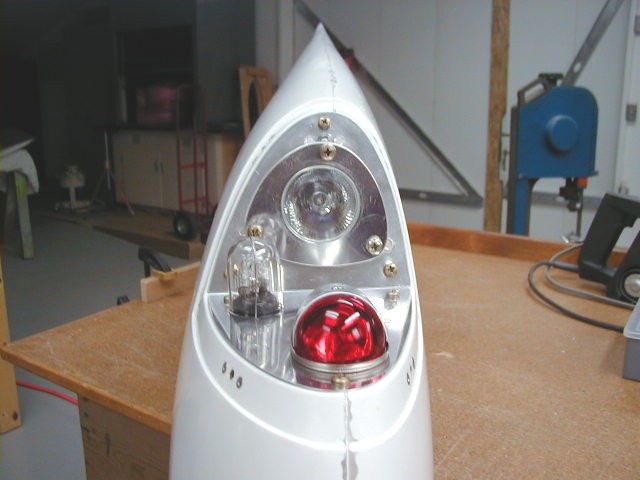
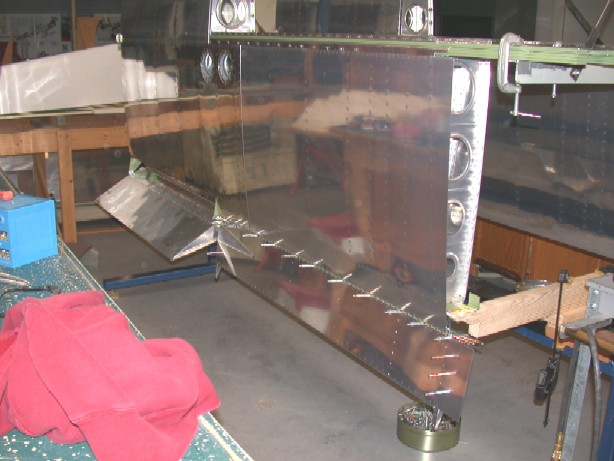
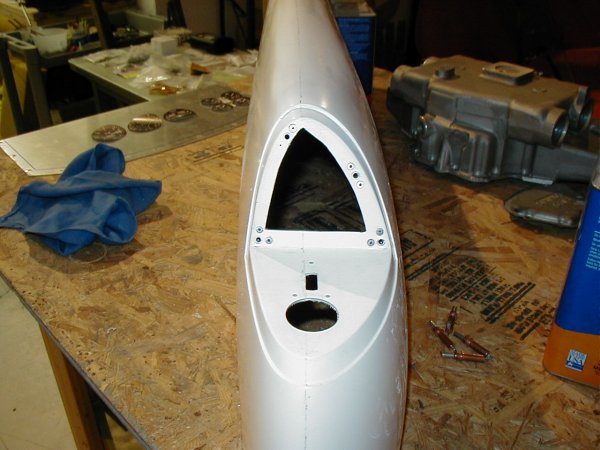
Here's my answer to the expensive strobe/nav light problem. I am using Van's sheared RV-7 wingtips that come with the provision for leading edge nav lights . I covered the area underneath the lexan wingtip lens with aluminum. The aluminum serves to reflect the light out into the world and is a bit more convenient to mount the components on.
I decided to try to shoehorn everything into the nav light area since I wasn't keen on cutting a hole in each wing for the landing light. I have seen a few other similar wingtip installations (below) but wasn't really sure if heat would be a problem. I also tried to spend the minimum amount of cash possible to get a suitable system.
There are a zillion combinations that will give you a suitable strobe/nav light package. A complete Whelen system (p/n LN SYS6) from Van's costs $713 and has a combo position/strobe for each wing and a combo strobe/white light for the tail. $713 OUCH!
I did a little research and decided to try a Whelen police car strobe system (p/n SPS660CCCC) from Strobes n' More from Strobeguy . The system was a relatively miserly $199 and came with 4 strobe heads, so I have 2 spares. The unit has 9 flash patterns. I purchased a $112 combo strobe/white light (p/n LN A500-14) for the tail from Van's. It is completely compatible with my power supply. I also bought a red position light (p/n LN W1285-PR-14) and a green position light (p/n LN W1285-PG-14) from Van's for $65 each. The total for my strobe/nav lights was $441... and I have 2 extra flashtubes left over for future replacement. Not too bad.
My research indicated that genuine Whelen aviation strobes put out from 12 to 25 joules. My unit is rated for 15 joules... I think. The data for different strobes is hard to compare because some specifications are in watts, some are in joules, and still others list only candlepower. All I know is that my setup is blindingly bright. Good enough.
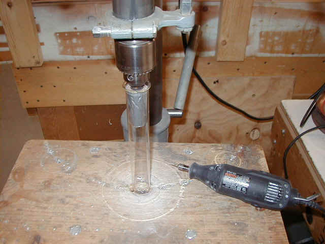
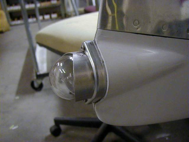
I decided to put a glass lens over my strobe flash tubes, although it might not be necessary since the lexan wingtip lens should protect it from the elements. Rather than spend $18 each for the bona fide Whelen parts, I decided to scrounge some suitable Pyrex test tubes from the lab. I chucked them up in my drill press and cut them to length using a diamond bit in my Dremel tool. Spinning the test tube while cutting with the Dremel tool makes it easy to get a straight cut. After cutting them to length I fire polished the rough edge with MAPP gas from a propane torch. Worked great. A loop of safety wire holds it in place nicely.
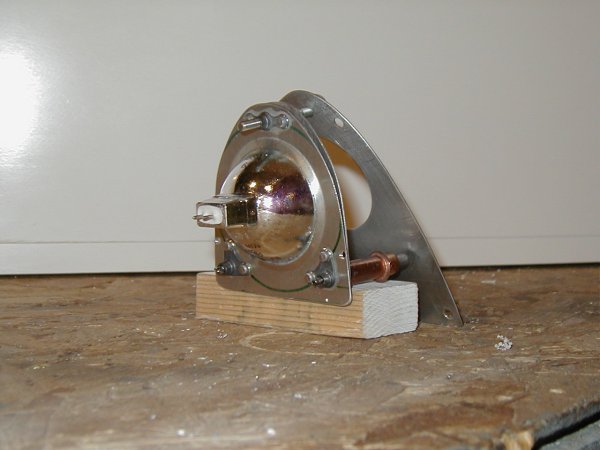
The landing light idea was stolen shamelessly from Terry Jantzi and others. IIRC, Terry claims to have used his similar landing lights for 700 hours without a bulb failure. That's far longer than most aviation landing light bulbs last. And the really cool part is that these bulbs come from Home Depot for $6 each. They are MR-16, 71 watt, 12 volt, halogen spot lights. You can get 100 watt bulbs also. I don't know if it would be too hot though. Haven't tried it.
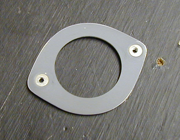
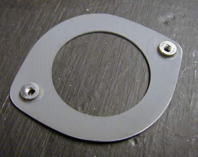
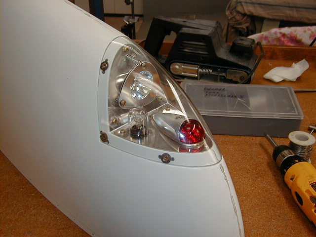
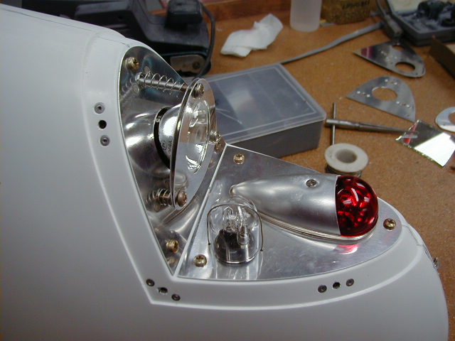
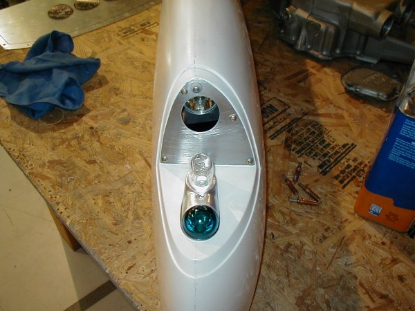
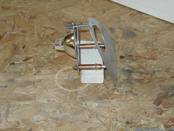
The pictures above show the landing light installation and should be self explanatory, but I'll hit the high points anyway. The bulb is held between two similar pieces of aluminum. The front piece has a slightly smaller hole in it than the rear piece. The rear piece nestles the bulb and the front one keeps it restrained.
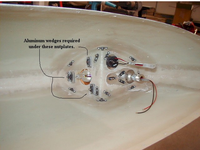
The aim adjusting screws are screwed into nutplates mounted on small aluminum wedges. The wedges keep the screws pointed forward, otherwise the screws would be perpendicular to the wingtip that they mount on and that simply won't work since the screws will hit the lexan cover.
The lexan wingtip lens is easily trimmed with scissors and belt sanded into submission.
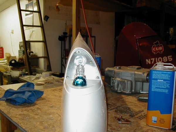
After everything was complete, I smoke tested the entire setup for 20 minutes with the lexan cover installed. Nothing melted. In fact, it didn't even get very warm. This was in my shop in still air at about 65 degrees.
The photo of the inside of the wingtip shows why this simple project ate up 2 evenings to complete.... gee whiz, only 18 nutplates per side! Heck, now I've got to decide whether to build the other wingtip the same way or try something different like Bill Von Dane has done. See below.
12-17-2001: Well, I decided to redo the first landing light assembly and build them very similar to what Bill Von Dane had done. I already had 90% of the work done and it wasn't difficult to reverse the mounting. So, now I have a nice set of lights, finished, and recessed into the wingtip as shown below. I am quite pleased with them.
Update 3-8-2002: I've had a zillion questions about these lights. Here's a bit more info.
If you went to Home Depot and got the correct 71 watt, 12 volt, MR-16 type bulb you should have no problems.
Each bulb will draw about 6 amps, so you can hook both bulbs (one on each wing) into a simple SPST toggle switch. SPST means "single throw, single pole". It's the simplest switch there is, just on or off. Get a switch rated for about 12V and 20 amps. You can get these at Radio Shack or almost anywhere.
Take the 12 volt positive from your buss, battery or wherever you're hooking into and run it to one side of the switch. Connect the other side to each light using a separate wire to go to each.
Connect the other side of the bulb to ground somewhere (negative side of the battery).
To actually connect the bulb you can either solder the wires to the bulb or get the proper connector from an electrical supply house. Or scavenge one off of a light fixture.
If you solder wires to the bulb you'll need to support the wires so they don't vibrate and break off. If you use a connector you'll want to safety wire it on so it doesn't fall off.
Having said all that, you can also get a kit from Bill Von Dane mailto:bill@vondane.com . See below or click on: http://vondane.com/rv8a/landlightkit/index.htm
I called Top Bulb company at 800-867-2852. They can special order (probably any lighting house can too) a 75 watt 12 volt double contact base spotlight type bulb for $12.50 each. They might have floodlight type too, but I didn't ask. The advantage of the double contact base is that it uses a connector like you'd find on a car. It twists and snaps into place. They don't carry the connector, but you should be able to get that at Autozone or a lighting supply house, maybe even Radio Shack.
I also bought a wig-wag flasher from Strobes n' More from Strobeguy . I plan to flash the landing lights while flying also. Vince Frazier *end of comment*
Bill Von Dane did his slightly differently. These pictures show a work in progress. Bill said he was going to move the strobe up slightly so it doesn't block the landing light beam. Vince Frazier *end of comment*
In the pictures the landing light is set back in the tip much farther than they will be once I'm done... I am thinking I may just put a rubber hose over the top screw, between the front plate and the light plates, to hold it all in place but still offer some movement for adjustment, and use the springs on the bottom "adjusters"... The top will probably be something like 1/4" from the front plate, or at least as close as I can get it and still allow it to pivot...
I had already cut holes in the tips for the NAV/Strobes to mount centered, but now seeing my install, looking at the picture you sent me, and reading what you said, I know I can angle the aft (strobe) end of the light up so the landing light will clear it with no problems...
I ended up getting the connectors I needed at a lighting shop here in town that also stocks the 71 watt and 100 watt bulbs, and since my bulbs will be in the wing tip, which I am sure can handle more heat that the lexan cover, I will probably go with the 100 watters...
I have also installed a home grown wig-wag circuit for my lights which you can see on my web site if you're interested. Bill Von Dane
*end of comment*
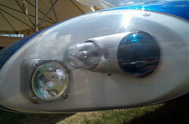
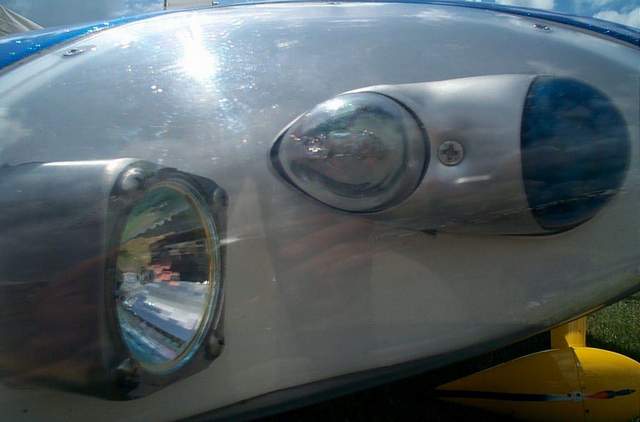
I'm not sure whose Rocket this is. A very nice installation. I can't tell from the photo how they adjust the aim of their landing light though. Vince Frazier *end of comment*
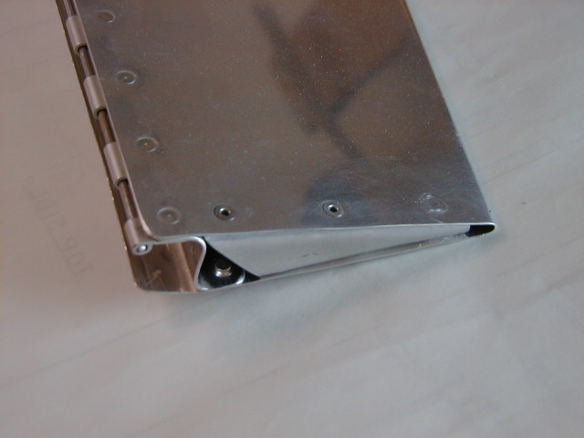
Here's a shot of the wingtip rib. It's installed backwards with the flush side toward the aileron. I'll install it with pop rivets.
Wingtip lockers:
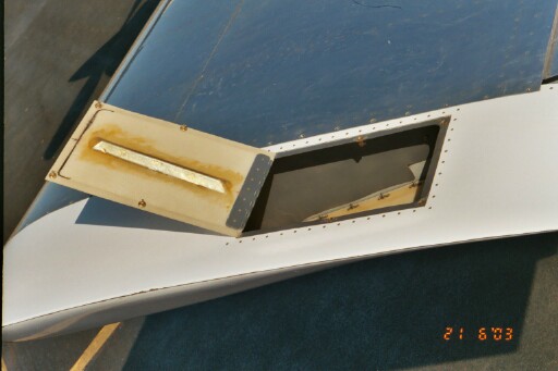
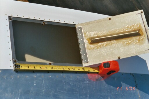
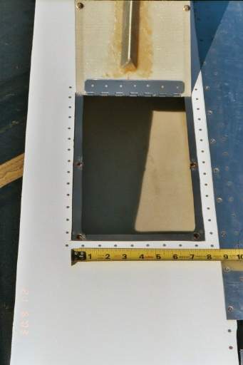
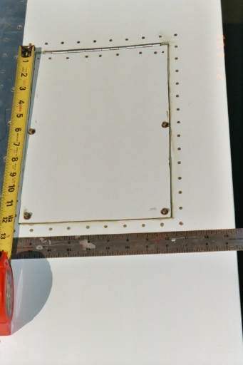
Here's a few shot's of a wing locker installation sent to me by Jack "Kabong" Starnes.
Vince Frazier *end of comment*
Return to the homepage: http://www.vincesrocket.com/
Last updated: 09/01/06
CAUTION: This web site is not a publication of, nor approved by, Harmon LLC, Team Rocket, Van's Aircraft or any other person or entity listed herein, except me. Be advised that I am a blithering idiot with neither brains nor money and my advice is not to be trusted. So there. You have been warned! Vince